
Instructions / Assembly

9
ASSEMBLY INSTRUCTIONS
5
C
BB
C
4
5
6
D
DD
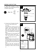
4. Attach Lower Pole assembly (F)
to Cylinder Housing Assembly
(G) using M6 x 10 mm bolts
(EE),and then put Beauty Ring
(E) through the Lower Pole
assembly on top of Cylinder
Housing Assembly (G).
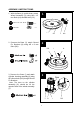
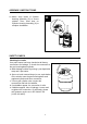
5. Screw Reflector Spacers (BB) into
the top of Burner Assembly (C).
6. Feed the valve and gas hose and
connect the Burner Assembly (C) to
the Upper Pole (D).
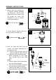
6.1. Feed the valve and gas hose into
and go through the Upper Pole (D).
6.2. Align the screw holes and secure
Burner Assembly (C) onto Upper
Pole (D) with M5 x 8 mm Bolts
(DD).
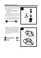
Notes:
a. Open the igniter cap by unscrewing
the cap counterclockwise.
b. Take out the AAA-battery included in
the pack with instruction manual.
c. Insert the AAA-battery to the igniter.
d. Screw the igniter cap back clockwise
G
EE
E
F
x 4
M6 x 10 mm Bolt
EE
Back
x 3
Reflector Spacer
BB
DD
AAA-Battery
Igniter
-
+