
Instructions / Assembly
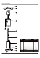

ASSEMBLY INSTRUCTIONS
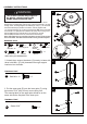
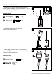
7. Unscrew stainless steel bolts M6 x 10 (CC) from
head assembly.
7
9
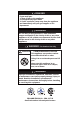
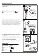
9-1. WARNING: Remove protective cover before
assembling.
Note: If necessary for proper alignment of reflector
sections, loosen each bolt prior to further assembly
and retighten after sections are aligned.
B
A
8. Insert hose of head assembly into pole. Secure
head assembly to pole with stainless steel bolts.
Note: The control knob on head assembly should
be above the decal on pole. When applicable,
visually checking portions of the hose assembly
located within the confines of the heater post.
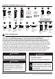
Hardware Used
CC
x 4
Stainless steel bolt
Note: CC pre-assembled in C
M6 x 10
CC
7
C
8
Hardware Used
GG
HH
II
9-2. Slide two reflector panels together.
Insert one screw M6 x 10 (HH). Slide one washerĭ6
(GG) over threaded end of screw M6 x 10 (HH) and
screw on cap nut (II) loosely.
x 9
x 9
x 9
Screw
M6 x 10
Washerĭ6
Cap nuts
II
GG
HH