
Use and Care Manual

6
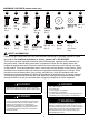
ASSEMBLY INSTRUCTIONS
Hardware Used
2
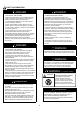
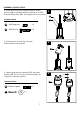
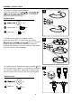
2. Attach three support brackets (I) loosely to base with
three bolts M8 x 16 (AA) downward through support
brackets into the Base.
AA
Bolt M8 x 16
x 3
AA
KK
H
I
G
Hard
3
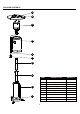
3. Put the upper pole (G) onto the lower pole (H), using
2pcs screw 3/16” (KK) to firmly secure 2pcs pole.
The warning label on the upper pole should be on the
same side as the flat plate of the lower pole.
ware Used
KK
x 2
Screw 3/16”
Hardware Used
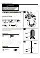
1. Reverse the base (J), fix the ground fixer (LL) to the base
Secure the ground fixer (LL) with two nuts M6 (NN). Fix
another two ground fixer (LL) with bolts and nuts, and
reverse the base (J).
Note: Nails 1981-RTLL for anchoring the base securely to
the ground are not inculded.
OO
x 1
Wrench
1
J
MM
LL
NN
GG
x 6
x 6
x 6
x 3
LL
MM
GG
NN
Bolt M6 x 10
Ground Fixer
M6 Nut
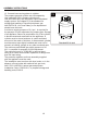
WARNING
This product contain sharp edges on
the panels cylinder housing and
handle please install with care.