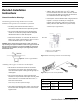
Water Softener Models: SA-HB-40-DB-CERT SA-HB-48-DB-CERT � �������� DuraResin Blend � ��������� M ad e with Pride in the USA ®
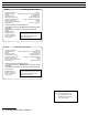
MODEL: SA-HB-40-DB-CERT Water Softener Operating Temperature: 34o–120o F Operating Pressure: 20–60 psi (#5 injector); 61-120 psi (#4 injector) Voltage: 110V 60 cycles Rated Service Flow: 15.2 GPM @ 15 psi Rated Softening Capacity: 14.2 @ 3.0 (#5 injector) (Kilograins / Pounds of Salt) 24 @ 7.5, 37.0 @ 15 (#4 injector) Max Flow Rate to Drain: 4.0 GPM 3 Amount of High Capacity Resin: 1.25 ft Rated Efficiency: 4,720 grains @ 3.0 lbs **Observe all state and local plumbing codes.
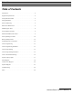
Table of Contents Table of Contents Introduction . . . . . . . . . . . . . . . . . . . . . . . . . . . . . . . . . . . . . . . . . . . . .4 Equipment Specifications . . . . . . . . . . . . . . . . . . . . . . . . . . . . . . . . . .4 Job Specifications Sheet . . . . . . . . . . . . . . . . . . . . . . . . . . . . . . . . . . .5 Sizing Information . . . . . . . . . . . . . . . . . . . . . . . . . . . . . . . . . . . . . . .5 Water Conditioning . . . . . . . . . . . . . . . . . . . . . . . . . . . . . . . .
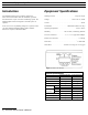
Introduction / Equipment Specification Introduction Equipment Specifications Your Hamilton Beach owner’s manual is designed to assist owners and installers with the installation, operation, and maintenance of your new water-conditioning system. The simplified photo format is designed to assist all aspects of operation. Working Pressure . . . . . . . . . . . . . . . . . . . . . . . . . . .
Job Specification Sheet / Sizing Information Job Specification Sheet Homeowner._________________________________________________ Dealer._______________________________________________________ Date of Installation.__________________ Installers Name. ____________________ Model #._____________________Serial #.
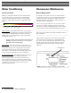
Water Conditioning / Homeowner Maintenance Occasionally you may find it necessary to initiate a manual regeneration. This is done by pressing the [REGEN] button on the front of the display. (See Figure 2.) When you press the [REGEN] button, the control performs a full regeneration of the water conditioner immediately. 0 5– 7. 3. Ex M tr em 1 0 el .5 y H + a g p rd g Hardness is comprised of dissolved calcium and magnesium.
Homeowner Maintenance (Continued) Calendar Day Override Feature Disinfection of Water Conditioners: Hamilton Beach systems have an optional calendar day override feature. The systems come pre-programmed with this feature turned off. To activate this feature, see Level II Programming instructions. This feature overrides the registered water volume and initiates a regeneration based on the days selected even if there has been 0 water usage registered.
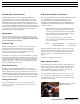
Manual Bypass Valve / Pre-Installation Check List Manual Bypass Valve (Optional) Your Hamilton Beach system is equipped with a manual bypass valve. (See Figure 4.) This valve is to be used if you want to stop the flow of water through the equipment but still allow untreated water into your home. Figure 4: Bypass valve. For example, a bypass valve may be used if a leak occurs in the system or when the homeowner(s) will be gone from the home for an extended period of time.
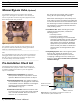
Detailed Installation Instructions Detailed Installation Instructions General Installation Warnings The following general warnings should be observed when installation and/or general service maintenance is performed. • Plumbing connections should be done in accordance with state and local plumbing codes. • A Brine Tank over-flow line of 1⁄2” ID 5/8” OD is recommended for the brine tank. This line should run from the barb fitting on the side of the tank to an unobstructed drain. (See Figure 7.
Start-up Rinsing Procedure Start-Up Rinsing Procedure (Bypass valve is optional) 1. With the plumbing, drain line, and overflow connections completed, slowly open the water supply allowing the lines to pressurize. Note: The optional bypass should still be in bypass mode as shown in Figure 9. Once the air clears and water begins to run to the drain, open the inlet valve (only) to the full open position and allow the water to run to the drain in purge for a minimum of 20 minutes. (See Figure 11.
Start Up Rinsing Procedure (con’t) 5. After the ten-minute backwash cycle, manually advance the control valve to the brine refill position for ten minutes allowing water to flow into the brine storage tank. (See Figure 13.) 7. Plug in the control valve. (See Figure 15.) Figure 15 Figure 13 Once water begins to flow into the tank fill the brine tank with a minimum of 100 lbs of salt pellets. 6. After the ten-minute refill time, manually advance the control valve to the service position. (See Figure 14.
Battery Backup/ Programming the Control Valve Battery Backup Feature Your Hamilton Beach softening system has a battery backup feature that allows the control to continue monitoring water flow and maintain the proper time of day during short power outages. The control uses a standard 9-volt battery (not supplied). During a power outage, the display will be turned off and the motor will not run, but the control will continue to monitor water flow.
Programming Guide Level I Programming Level I Programming Parameters Parameters P1 Time of day P2 Time of regeneration P3 Water hardness (grains per gallon—gpg) P4 Salt usage per regeneration (lbs) P5 System capacity (Kg) P1 Time of Day AM or PM Ranges: 1:00 to 12:59 or 00:00 to 23:59 Minimum Increments: 1 Min. Table 3: Level I programming parameters overview.
Programming Guide Changing the Settings To change the settings press the [SET] button on the far right. The digit of the display starts flashing. If you want to change this number, press the up arrow [# ] button to increase the number or the down arrow [$ ] button to decrease the number. To skip the number without changing, press the left arrow [! ] button. When you reach the far left digit, pressing the left arrow [ ! ] button will return you to the far right digit.
Programming Guide Level II Programming The Level II programming has been programmed by the manufacturer to the settings in Table 6. The changing of preset values can be done at this time. Refer to Level II programming parameters in Table 6 for options. Note: It is not recommended that homeowners change these values without checking with local water-treatment professional for details. Incorrect programming can cause system malfunction and the possible need for a field service call to reprogram the system.
Programming Guide Level I and II Default Settings The following table represents preset values programmed into the systems at the factory for both levels I and II for the model shown. (See Table 7.) Level I Parameters Name Description SA-HB-40-DB-CERT SA-HB-48-DB-CERT P1 Time of day Set in field Set in field P2 Time of regeneration 2:00 a.m. 2:00 a.m. P3 Hardness Set in field Set in field P4 Salt amount 3.0 lbs 4.0 lbs P5 Capacity 14.1 Kgr @ 3.0 lbs of salt 15.2 Kgr @ 3.
System Capacity Inputs System Capacity Inputs SA-HB-40-DB-CERT SA-HB-40-DB-CERT 3.0 14.140 SA-HB-48-DB-CERT n/a 3.6 15.5 15.248 4.0 16.5 15.5 5.0 19.0 18.0 6.0 22.0 21.0 7.0 24.0 23.5 7.5 24.440 24.3 8.0 25.6 25.0 9.0 27.9 26.148 10.0 30.0 30.0 11.0 31.9 31.5 12.0 33.6 33.0 13.0 35.1 34.0 14.0 36.4 35.2 15.0 37.140 36.0 16.0 38.4 37.0 17.0 39.1 38.0 18.0 39.6 39.848 19.0 39.9 41.0 20.0 40.0 41.5 21.0 n/a 42.0 22.0 n/a 43.0 23.0 n/a 44.
Flow Diagrams Flow Diagrams Figure 20 18 | Hamilton Beach Owner’s Manual Figure 22 Figure 21 Figure 23
Flow Diagrams Figure 24 Figure 25 Figure 26 Hamilton Beach Owner’s Manual | 19
Control Valve Diagram Control Valve Diagram 20 | Hamilton Beach Owner’s Manual
Control Valve Parts Code Part Number Description 1 AVP-1034448 Valve Body Assembly Qty 1 2 AVP-1034347 AVP-1034346 Motor Drive Assembly, 60 Hz Motor Drive Assembly, 50 Hz 1 3 AVP-1034424 Control Assembly, 1000i 1 4 AVP-1034362 AVP-1034363 Cam Gear, 1100 English Cam Gear, 1100 Symbols 1 5 AVP-1032881 Bracket 1 6 AVP-1005001 Screw, 10-32 x 1/2 inch 1 7 AVP-1033670 Turbine Group 1 8 AVP-1034340 10-inch Brine/backwash Control 1 9 AVP-1032988 Injector Screen Assembly 1 10
Systems Diagram Systems Parts Systems Diagram SA-HB-40-DB-CERT Code 14 Part Number Description Qty 1 AUV-1050643 Hamilton Beach Valve 1 2 MTK-SP-1044 10x44 Mineral Tank 1 3 DST-1080 Hamilton Beach Distributor, 10x44 1 4 MP-TECH 40DB Resin Media, 1.
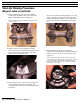
Troubleshooting Troubleshooting Manual Indexing for Each Regeneration Errors The control valve may be manually indexed to each regeneration position as follows: 1. Remove the control valve cover. 2. Press down on the top of the drive gear to disengage the cam gear. (See Figure 9 on page 10.) 3. With the cam gear disengaged, rotate the cam gear counterclockwise to the various positions, using the same steps as the Start-up Rinse procedure (see page 10).
Troubleshooting Troubleshooting Procedures Problem Description Possible Cause Solution • Capacity display stays at “9999” even though there is water usage Total system capacity was calculated to be a value greater than 9999 As the water usage continues, the remaining capacity will drop below 9999—then other values will be shown • Control does not respond to [REGEN] button Button is not active in the programming mode Refer to the regeneration section • Control does not display time of day Transfor
Troubleshooting Problem Description • Control does not regenerate automatically but does regenerate when [REGEN] button is depressed • Run out of soft water between regenerations • Control does not draw brine • Brine tank overflow • Intermittent or irregular brine draw • No conditioned water after regeneration Possible Cause Solution If water flow display is not operative, refer to item 5 (“No water flow display when water is flowing”) in this table Refer to item 5 (“No water flow display when wate
Troubleshooting Problem Description Possible Cause Solution • Control backwashes at excessively low or high rate Incorrect backwash controller Replace with correct size controller Foreign matter affecting controller operation Remove and clean controller • Flowing or dripping water at drain line or brine line after regeneration Drain valve (2 or 6) or brine valve (1) held open by foreign matter Manually operate cam gear to flush out foreign matter holding disc open Weak valve stem return spring o
Notes Hamilton Beach Owner’s Manual | 27
Notes 28 | Hamilton Beach Owner’s Manual
Notes Hamilton Beach Owner’s Manual | 29
Notes 30 | Hamilton Beach Owner’s Manual
Notes Hamilton Beach Owner’s Manual | 31
B R A N D D E S I G N G U I D E Logo U © 2005 R&M Water Group. Water Technologies, Inc.. and R&M Water Group are branded trademarks of Water Technologies, Inc. All rights reserved. Logo: Material produced by Water Technologies, Inc. and authorized by Black Hamilton Beach.