PLATINUM PLUG N PLAY 350Z USER MANUAL VERSION 1.6 FIRMWARE: 350Z V1.0.0 SOFTWARE: ECU MANAGER V 1.0.0 Prepared Date NSC 13/03/08 Path: Filename: Title: Firmware Software 350Z v1.0.0 v1.0.0 Haltech Platinum Series - 350Z User Manual Document Number: 1.
User Manual – Haltech 350Z WARNING: AFTERMARKET ENGINE MANAGEMENT THIS ECU IS DESIGNED AND SOLD FOR RACING USE ONLY. USING THIS PRODUCT FOR STREET/ROAD USE MAY BE PROHIBITED BY LAW. PLEASE CHECK WITH YOUR LOCAL VEHICLE AUTHORITY BEFORE USING THIS PRODUCT. 1.
User Manual – Haltech 350Z TABLE OF CONTENTS 1. INTRODUCTION..............................................................................................................................5 2. THE ECU..........................................................................................................................................5 2.1 ECU Overview........................................................................................................................5 3. THE ECU PATCH HARNESS...........
User Manual – Haltech 350Z 6.2.3 The Axes Setup .......................................................................................................................27 6.3 6.4 6.5 6.6 Copy through Feature...........................................................................................................29 Knock detection....................................................................................................................30 Tuning Pages (Tabs).........................................
User Manual – Haltech 350Z 1. INTRODUCTION Welcome to your new Haltech Platinum Plug n Play ECU. 2. THE ECU 2.1 ECU Overview Figure1. The Haltech ECU Figure2. The ECU showing the Main Harness Connector Figure3. The ECU showing External MAP sensor port, CAN & USB Connector 1.
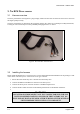
User Manual – Haltech 350Z 3. THE ECU PATCH HARNESS 3.1 Harness overview The ECU patch harness is designed as a plug and play solution for the 350Z. It allows the user to have control of the engine quickly & easily. The ECU patch harness is designed for the supported vehicles only. Please do not attempt to modify this harness, as doing so will void warranty as well as potentially damaging the ECU or vehicle. Figure4. The 350Z ECU Patch harness 3.
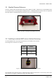
User Manual – Haltech 350Z 3.3 Manifold Pressure Reference The ECU is fitted with an internal MAP sensor rated to 22PSI (150 KPa). Alternatively an external MAP sensor can be fitted to the ECU allowing higher manifold pressures. A Manifold Absolute Pressure sensor is required for all tuning methods. The Manifold Pressure Reference can be set in the Main Setup Page. Figure3. The ECU showing External MAP sensor port 3.3.
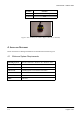
User Manual – Haltech 350Z 3.4 Auxiliary Outputs The ECU has two Auxiliary Outputs that can be configured via the ECU Manager. Both outputs can be found on the 3 POS AMP connector fitted to the Patch Harness. The wiring for this connector is as follows: Position Function 1 Boost Solenoid Output (Aux Out 1) 2 +12V 3 AUX Out 2 Figure5. The Auxiliary Output Connector (3 Position) 3.4.
User Manual – Haltech 350Z Position Function 1 Aux Rev Limiter Input 2 GND Figure5. The Auxiliary Rev Limiter Input Connector (2 Position) 4. INSTALLING SOFTWARE Please insert the ECU Manager Installation CD and follow the instructions given. 4.1 Minimum System Requirements Operating System: Windows 2000 SP4 / Windows XP / Windows Vista Processor Speed: 1GHz RAM: 256 Kb Video Card: 128MB graphics card with 3D acceleration USB: 1.1 Hard Drive: 250MB Other: CD Drive 1.
User Manual – Haltech 350Z THE ECU MANAGER To start the ECU Manager please click on the newly created ECU Manager desktop Icon to start the software. Figure 6: The ECU Manager desktop Area’s of Manager the ECU 1. ECU Navigator 2. Tuning Pages 3. Menu 4. Navigator Description Box 5. ECU Status indicator 6. Status Bar 7. Tuning Page with displays 1.
User Manual – Haltech 350Z 4.1 Communication To communicate with the ECU, please connect the USB cable between the ECU and the laptop. Select the connect/disconnect icon, or use the F5 key. Figure 7: The ECU Connect/disconnect icon. Once the ECU has been connected, the ECU manager will begin to download the data stored in the ECU. Once this download has been completed, the ECU status indicator will display “Connected” 4.2 Menu 4.2.1 File The file menu has options relating to the ECU tuning maps.
User Manual – Haltech 350Z 4.2.2 Edit Copy: Copies the currently selected values. Paste: Pastes the any copied values. 4.2.3 Setup Main Setup: Settings for the ECU configuration can be found here. Table Setup: Settings for the currently selected Tuning table can be found here. Security: The ECU’s security functions such as password protection can be configured here. Data Logging: Data Logging can be configured here. 4.2.4 Tools Firmware Version: The firmware version in the ECU can be checked here.
User Manual – Haltech 350Z 5. THE MAIN SETUP The Main Setup page allows the user to configure the ECU. The Main Setup page can be accessed by selecting the Setup > Main Setup in the Menu, or by pressing F3. The Main Setup page is split into two pages; the first page “Main” contains the critical engine running settings, with the second page “Inputs/Outputs” containing the settings for the Auxiliary functions. Figure 8: The Main Setup window 5.1 Tuning Configuration 5.1.
User Manual – Haltech 350Z Tuning Mode Depending on the Load source, the tuning modes available may change. Volumetric Efficiency (VE) Injection Time (mS) Lambda Correction (y) Volumetric Efficiency (VE): MA F MA P TPS VE tuning is available when MAP or TPS is selected as the Main Load source. VE or Volumetric efficiency allows the ECU to determine the injection time based on the Engine Capacity, Desired AFR, Injector Flow and Volumetric Efficiency table.
User Manual – Haltech 350Z WARNING: O2 CONTROL LIMITS SHOULD BE CONFIGURED SO THAT THE ENGINE AIR FUEL RATIO MIXTURES WILL STILL BE SAFE UNDER SENSOR FAULT CONDITIONS. 5.3 Over Boost Limiter Boost Control: This setting allows the Boost Controller to be switched on or off. Boost Cut Value: The boost cut value is the manifold pressure value at which the ECU will cut all fuel injection. This feature is to be used as an engine protection device only.
User Manual – Haltech 350Z WARNING: THE CURRENT CONTROL MUST BE SET CORRECTLTY. EXCESSIVE CURRENT PASSED THROUGH AN INJECTOR LOAD FOR A LONG PERIOD OF TIME MAY DAMAGE THE INJECTORS 5.6 Trim Settings Injector Trim Tables: This allows the injector trim tables to be enabled and viewed in the ECU Navigator. Ignition Trim Tables: This allows the ignition trim tables to be enabled and viewed in the ECU Navigator. Figure 8: The Input/Output Setup window 5.
User Manual – Haltech 350Z In this case, when either Knock or Coolant conditions were true, the RPM value will be checked, and if RPM is greater than 1000, the output would activate. When active, the ECU will output a ground or (0V) signal. 5.8 Boost Control The ECU has a built in boost controller. The boost controller allows the control of a turbocharger’s waste gate through a boost control solenoid (sold separately Haltech Part # 34800).
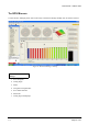
User Manual – Haltech 350Z 6. THE ECU NAVIGATOR The ECU navigator allows quick access to all tuning tables. 6.1 Selecting Tuning Tables The currently view tuning table can be changed at any time by the following methods. 1. Click on the desired table using the left mouse button. or 2. Using the Alt-UpArrow or Alt-DownArrow keys will change the currently viewed table. Figure9. ECU Manager with ECU Navigator The ECU Navigator menu can also be unpinned to allow more area on the tuning desktop.
User Manual – Haltech 350Z Groups The Navigator tree contains multiple groups. These groups are designed to differentiate the functions of the ECU and to gain quick access to related tuning tables. 6.1.1 Expanding / Contracting groups To expand the tree, click on the (+) with the mouse, or alternatively using the keyboard, use the Alt-RightArrow keys. To contract the tree, click on the (-) with the mouse, or alternatively using the keyboard, use the Alt-LeftArrow keys.
User Manual – Haltech 350Z 7. MODIFYING TUNING TABLES WARNING: WHEN TUNING AN ENGINE, ESPECIALLY UNDER LOAD, IT IS ADVISABLE TO HAVE AN INDICATION OF THE AIR-FUEL RATIO AT WHICH THE ENGINE IS RUNNING. IT IS RECOMMENDED THAT A WIDE-BAND OXYGEN SENSOR BE USED FOR THIS SINCE IT DISPLAYS THE AIR-FUEL RATIO QUICKLY. All tuning tables in the ECU Navigator can be modified. Once a tuning table has been selected, cells can be selected and modified. 7.1.
User Manual – Haltech 350Z Figure 12: The text view table with all cells selected Ctrl-A — Will select all cells in the tuning table. When multiple cells are selected, cell operations will be applied to all cells. 7.1.2 Deselecting cells Deselecting cells can be done by holding down the Ctrl key, then any arrow key. For example, pressing Ctrl-RightArrow will reduce the selected area by one column, by deselecting the far left column. Ctrl SPACE— Will deselect all cells in the tuning table. 7.1.
User Manual – Haltech 350Z When in All ranges mode, using the A key will slightly change the way in which All ranges works. The area of selected cells is only set to above the current position. Figure 15: With All ranges enabled Figure 16: With All ranges above enabled 7.1.4 Currently used cell When the engine is running, the ECU will be using values from the tuning table. The value currently being used by the ECU is indicated by the reference marker.
User Manual – Haltech 350Z 7.1.5 Increasing / decreasing cell value Once a cell selection has been made, its value can then be changed. The following is how cell values can be changed. Cell values can be increased by using the PgUp key. Cell values can be decreased by using the PgDown key. If smaller changes are required the Ctrl key can be held down while adjusting cells. If larger changes are required the Shift key can be held down while adjusting cells. 7.1.
User Manual – Haltech 350Z Figure 17: Selected cells before linearizing Figure 18: Selected cells after linearizing 7.1.9 Copying and Pasting cells At any time cells can be copied and pasted like any other windows application. To copy a cell selection, use the Ctrl-C keys or the (insert copy icon here) icon. To paste a cell selection, use the Ctrl-V keys or the (insert paste icon here) icon. Cell values can be copied between tuning tables if the selection area and type are the same. 7.1.
User Manual – Haltech 350Z Figure 19: The Insert new axis point dialog Please note once the predefined maximum number of axis points has been reached, the insert & delete icons will appear grayed out. 7.2.2 To delete an existing axis point To delete an axis point, select the Delete key. A delete dialog will appear. It will prompt you to delete either the current row/s or column/s. Figure 20: The Delete axis point dialog 7.2.
User Manual – Haltech 350Z Access to the Axes Setup can be made by right clicking on the Tuning table, or by pressing the F3 key. Figure 21: The Axis Setup dialog 1.
User Manual – Haltech 350Z 7.3 Copy through Feature The copy through feature allows the Haltech ECU to output the factory ECU’s fuel and ignition timing values, wherever the user specifies. This feature allows mildly modified engines to retain the factory operation without having to tune the entire ECU. Copy through can be enabled in the Base Fuel & Base Ignition tables by pressing “C” in the desired cells. Multiple cells can also be selected and set to Copy through.
User Manual – Haltech 350Z 7.4 Knock detection The 350Z ECU has a built in knock detection circuit that allows the filtered output of the knock sensor to be viewed and logged via the Knock Level Display channel. Knock Level Display – When knock is detected which exceeds the noise threshold, then spikes will appear in this trace. The height of the spike indicates how severe the knock event was. Knock Signal – This is the raw signal from the Knock sensor. It is only displayed as a reference.
User Manual – Haltech 350Z 7.5 Tuning Pages (Tabs) The ECU Manager allows the user to setup multiple tuning pages, or tabs. These tuning pages can be configured individually and populated with displays. To move between Tuning Pages, use the Tab key or alternatively click on the required tab with the mouse. Tuning Pages can be added as well as renamed, copied and deleted by right clicking on the desired tab. 7.
User Manual – Haltech 350Z To customise a display, right click on the display itself or the displays tooltip associated displays options. , which will reveal the 7.6.1 Dial Gauge The dial gauge is an analogue representation of an ECU channel. The displayed channel can be changed by right clicking on the display. 7.6.2 Bar Gauge The bar gauge is a graphical display that allows an ECU channel to be viewed as a rectangular bar. The displayed channel can be changed by right clicking on the display. 7.6.
User Manual – Haltech 350Z Channels can be added and removed by right clicking on the display. 7.6.4 Number Display The number display allows an ECU Channel to be boldly displayed. The label on the number display can be hidden, which is useful when number displays are combined with dial gauges. The displayed channel can be changed by right clicking on the display. 7.6.5 Trace Display The trace display shows the graphical history of any selected ECU channel.
User Manual – Haltech 350Z Trace History The trace display has the option of allowing the user to view the history of the currently displayed channels. The trace history can only be viewed when the display is paused. A scroll bar will appear, allowing the user to move along the trace history. This feature can be enabled in the Tools>Options>Appearance window. 7.6.6 Text View The text view allows the selected tuning table to be displayed as a spreadsheet.
User Manual – Haltech 350Z 7.6.7 2D View The 2D view allows the selected tuning table to be displayed as a slice. The tuning table can be navigated by using the arrow keys, and the cell value modified by using the pgUp & pgDown keys. The currently selected cell can be seen below highlighted in blue, with the current engine position indicated by the blue arrow. The slice info can be seen in the left column.
User Manual – Haltech 350Z blue arrow. The current selection size is indicated in the top right hand corner, with the currently selected cells value shown on the left. The Output Value shown in the bottom right of the display indicates the value that this table is producing. This value is linked to this table only and may not represent the final value used by the ECU, as correction tables may affect any final values.
User Manual – Haltech 350Z Appendix 8. SPEED – DENSITY FUEL CALCULATION & VE TUNING The Speed-Density algorithm is a method of calculating fuel injection pulse width for a given engine speed and load. The VE table is a table that describes the volumetric efficiency of an engine. If you wish just learn how to tune the VE table, then jump ahead to the Tuning a Car by VE and the SpeedDensity Calculation section.
User Manual – Haltech 350Z the volume of air, we are really interested in knowing the number of molecules of air that we have. In order to determine this, we apply the Air Temperature and Manifold Pressure from the manifold to the volume of air that managed to get inside the cylinder. 8.3 Calculating the amount of Fuel Given that the amount of air in the cylinder is now calculated, we can now use the Air Fuel Ratio Target to determine how much fuel is required.
User Manual – Haltech 350Z 9. TUNING A CAR BY VE AND THE SPEED-DENSITY CALCULATION 9.1 Setting up the Parameters Before tuning the VE table, it is very important that you set all the supporting parameters and tables as accurately as possible, otherwise your VE table will not calibrated correctly and you will lose many of the advantages of this tuning method. 1. Load source – Select MAP. 2. Manifold Pressure Source – Choose Internal or External senor. 3.
User Manual – Haltech 350Z vehicle has been calibrated satisfactorily, then changing the target AFR will change the engine to operate sufficiently close to the new AFR to only require minor tuning or checking. This is far quicker than the trial and error method required when manipulating injection times directly. Similarly, if injector sizing is changed, then a change to the injector flow and dead time parameters will adjust the fuelling to suit the new injectors.
User Manual – Haltech 350Z 10.
User Manual – Haltech 350Z R Enables/disables “All ranges” mode. T Enables/Resets/Disables Trace in Text View W Same as Q, but operation will also be performed to the cell above and across the current cell.
User Manual – Haltech 350Z LIMITED WARRANTY Lockin Pty Ltd trading as Haltech warrants the HaltechTM Programmable Fuel Injection System to be free from defects in material or workmanship for a period of ninety days from the date of purchase. Proof of purchase, in the form of a bill of sale or receipted invoice, which indicates that the product is within the warranty period must be presented to obtain warranty service.
User Manual – Haltech 350Z REVISION HISTORY Date Version Author Changes 12/09/07 1.1 NC Updated All ranges, axes setup and Rev limit settings. 22/11/07 1.3 NC Updated Axes Setup 29/11/07 1.4 NC Added warnings, knock instructions, aux i/o 1.6 1.