
Manual


IQ3 Data Logger Dash Installation Manual
20
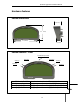
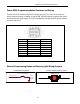
BUTTON WIRING DIAGRAM
chassis
ground or
IQ3 pin 4
to IQ3 connector
PUSH BUTTON SWITCH
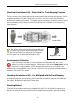
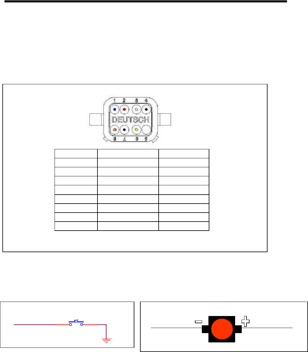
Power/RPM/Programming Button Connector and Wiring
The rear of the IQ3 contains an 8 position Deutsch connector. This connector provides the
power and ground inputs, in addition to engine RPM, optional external program button inputs
and external warning light output. The IQ3 is provided with the appropriate 8 position mating
connector and wiring.
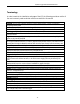
Pin Number Function Wire Color
1 Button 1 BLUE
2 IQ3 Power RED
3 Button 2 WHITE
4 Button Ground BLACK
5 Do Not Use NOT USED
6 Tach YELLOW
7 IQ3 Ground BLACK
8 External Warning ORANGE
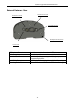
External Programming Button and Warning Light Wiring Diagram
EXTERNAL WARNING WIRING DIAGRAM
to 12v vehicle power to IQ3 connector pin 8
WARNING LIGHT