
Manual
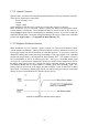
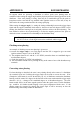
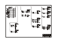


Table Of Contents
- Introduction
- SECTION 1 Getting Started
- CHAPTER 1 HALTECH IG5 INSTALLATION
- 1.1 Overview
- 1.2 Installation Summary
- 1.3 Expanded Installation Guide
- 1.3.1. Manifold Absolute Pressure (MAP) Sensor
- 1.3.2. Coolant Temperature Sensor
- 1.3.3. Inlet Air Temperature Sensor
- 1.3.4. The Throttle Position Sensor (TPS)
- 1.3.5. Mounting the Igniter
- 1.3.6. Route Wiring Harness and Connect Sensors
- 1.3.7. Power Relays
- 1.3.8. Electronic Control Unit (ECU)
- 1.3.9. Flying Leads
- 1.3.10. Install and connect any Optional Outputs
- 1.3.11 Connect the Trigger Sensor
- 1.3.12 Connect the ECU
- CHAPTER 2 GETTING ONLINE
- CHAPTER 3 ENGINE IDENTIFICATION
- CHAPTER 4 USING HALTECH SOFTWARE
- CHAPTER 5 STARTING THE ENGINE
- CHAPTER 1 HALTECH IG5 INSTALLATION
- SECTION 2 Other Adjustable Features
- SECTION 3 Software Features
- SECTION 4 IG5 Optional Outputs
- CHAPTER 12 SOFTWARE ACCESS
- CHAPTER 13 AUXILIARY OUTPUTS
- 13.1 Description
- 13.2 Turbo Waste Gate Control (TWG)
- 13.3 Dual Intake Valve Control (DIV)
- 13.4 Torque Converter Lockup (TCC)
- 13.5 Electric Thermatic Fan Control (TF)
- 13.6 Electric Intercooler Fan Control (IF)
- 13.7 Shift Light Illumination (SL)
- 13.8 Anti-Stall Solenoid Control (AS)
- 13.9 Turbo Timer (TT)
- 13.10 NOS Switch
- SECTION 5 Appendices
80
C.3.3 Twin Triggers and Twin Distributors
The Twin Trigger is designed for two purposes. It can be used to provide direct fire ignition
on 2 cylinder engines (most motorbike twins) without the use of a Home sensor. Here the
trigger input causes the IG5 to fire coil 1, and the home signal causes the IG5 to fire coil 2.
The Twin Trigger can also be used to differentiate between coils on an 8 or 12 cylinder using
twin distributors. Two of four (or six) cylinder distributors, complete with trigger wheels can
be used, thus again obviating the need for a Home.