
Manual
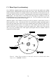
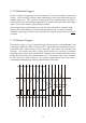


Table Of Contents
- Introduction
- SECTION 1 Getting Started
- CHAPTER 1 HALTECH IG5 INSTALLATION
- 1.1 Overview
- 1.2 Installation Summary
- 1.3 Expanded Installation Guide
- 1.3.1. Manifold Absolute Pressure (MAP) Sensor
- 1.3.2. Coolant Temperature Sensor
- 1.3.3. Inlet Air Temperature Sensor
- 1.3.4. The Throttle Position Sensor (TPS)
- 1.3.5. Mounting the Igniter
- 1.3.6. Route Wiring Harness and Connect Sensors
- 1.3.7. Power Relays
- 1.3.8. Electronic Control Unit (ECU)
- 1.3.9. Flying Leads
- 1.3.10. Install and connect any Optional Outputs
- 1.3.11 Connect the Trigger Sensor
- 1.3.12 Connect the ECU
- CHAPTER 2 GETTING ONLINE
- CHAPTER 3 ENGINE IDENTIFICATION
- CHAPTER 4 USING HALTECH SOFTWARE
- CHAPTER 5 STARTING THE ENGINE
- CHAPTER 1 HALTECH IG5 INSTALLATION
- SECTION 2 Other Adjustable Features
- SECTION 3 Software Features
- SECTION 4 IG5 Optional Outputs
- CHAPTER 12 SOFTWARE ACCESS
- CHAPTER 13 AUXILIARY OUTPUTS
- 13.1 Description
- 13.2 Turbo Waste Gate Control (TWG)
- 13.3 Dual Intake Valve Control (DIV)
- 13.4 Torque Converter Lockup (TCC)
- 13.5 Electric Thermatic Fan Control (TF)
- 13.6 Electric Intercooler Fan Control (IF)
- 13.7 Shift Light Illumination (SL)
- 13.8 Anti-Stall Solenoid Control (AS)
- 13.9 Turbo Timer (TT)
- 13.10 NOS Switch
- SECTION 5 Appendices
78
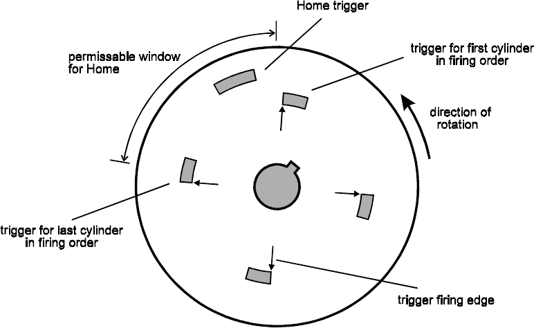
C.3 Home Signal (synchronising)
On a distributor equipped engine the IG5 does not need to know the number one cylinder
position because the distributor sends the spark to the correct plug. With Direct Fire, the IG5
needs to identify the number one cylinder position so that it knows to fire the number one coil.
To do this, the ECU needs to receive a synchronisation event which is usually provided by a
Home signal. This input needs to occur before the main trigger for cylinder (or coil) one,
indicating that the next trigger input is for cylinder one. The exact timing of the home pulse
is not critical but must precede the main trigger.
When the engine is first cranked over the ECU will not generate a spark until it receives a
home signal (sync event). After that, the ECU fires each ignition output sequentially until it
gets to the last output after which it will receive another home pulse which resets the ECU to
coil one and the sequence repeats. For example, on a four cylinder with waste spark, coil one
needs be fired once every revolution (ie twice per engine cycle). With 4 coils, coil one fires
once every two revolutions and a half engine speed signal from the camshaft would be
required for the Home signal.
Figure 6. Home Trigger position on cam angle sensor for 4 cylinder with a home
trigger every camshaft revolution