
Manual
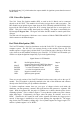
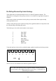

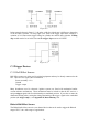
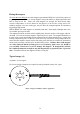
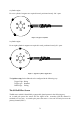
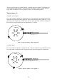
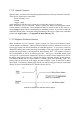
Table Of Contents
- Introduction
- SECTION 1 Getting Started
- CHAPTER 1 HALTECH IG5 INSTALLATION
- 1.1 Overview
- 1.2 Installation Summary
- 1.3 Expanded Installation Guide
- 1.3.1. Manifold Absolute Pressure (MAP) Sensor
- 1.3.2. Coolant Temperature Sensor
- 1.3.3. Inlet Air Temperature Sensor
- 1.3.4. The Throttle Position Sensor (TPS)
- 1.3.5. Mounting the Igniter
- 1.3.6. Route Wiring Harness and Connect Sensors
- 1.3.7. Power Relays
- 1.3.8. Electronic Control Unit (ECU)
- 1.3.9. Flying Leads
- 1.3.10. Install and connect any Optional Outputs
- 1.3.11 Connect the Trigger Sensor
- 1.3.12 Connect the ECU
- CHAPTER 2 GETTING ONLINE
- CHAPTER 3 ENGINE IDENTIFICATION
- CHAPTER 4 USING HALTECH SOFTWARE
- CHAPTER 5 STARTING THE ENGINE
- CHAPTER 1 HALTECH IG5 INSTALLATION
- SECTION 2 Other Adjustable Features
- SECTION 3 Software Features
- SECTION 4 IG5 Optional Outputs
- CHAPTER 12 SOFTWARE ACCESS
- CHAPTER 13 AUXILIARY OUTPUTS
- 13.1 Description
- 13.2 Turbo Waste Gate Control (TWG)
- 13.3 Dual Intake Valve Control (DIV)
- 13.4 Torque Converter Lockup (TCC)
- 13.5 Electric Thermatic Fan Control (TF)
- 13.6 Electric Intercooler Fan Control (IF)
- 13.7 Shift Light Illumination (SL)
- 13.8 Anti-Stall Solenoid Control (AS)
- 13.9 Turbo Timer (TT)
- 13.10 NOS Switch
- SECTION 5 Appendices
74
The set-up for this sensor is similar to the S1 except that one extra magnet is required as well
as the orientation being changed. The north pole of the magnet is used to generate the main
trigger while a south pole is used to generate the home or synchronisation pulse.
Typical setups (s2)
4 cylinder / 2 rotor engine
For a four cylinder 3 magnets are required in total. Two north poles positioned exactly 180°
apart while a south pole needs to trigger the sensor before the trigger for cylinder No 1. The
positioning of the magnet for cylinder one is done the same way as the for the S1 making sure
the north pole is triggering the sensor at approximately 75° BTDC.
Figure 4: Typical 4 Cylinder/ 2 Rotor Application
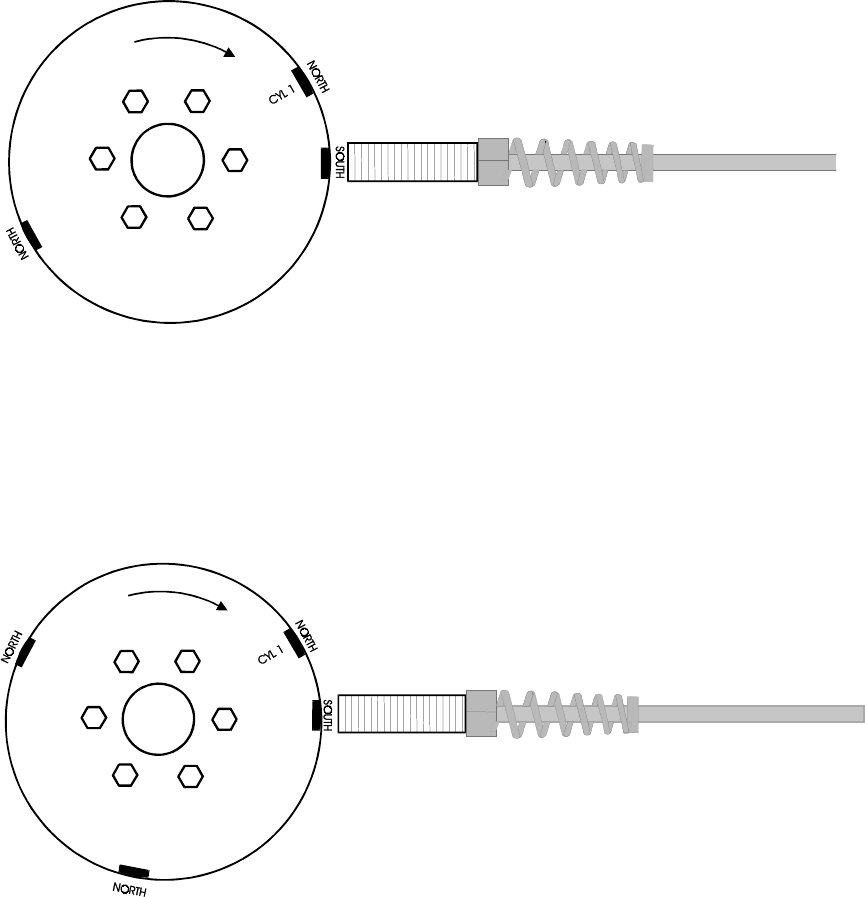
6 cylinder engine
For a six cylinder 4 magnets are required in total. The two north poles are positioned exactly
120° apart while a south pole need to trigger the sensor before the trigger for cylinder No 1.
Figure 5: Typical 6 cylinder/ 3 rotor application