
Manual
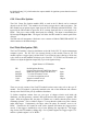
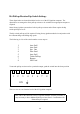

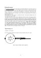
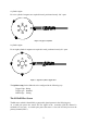
Table Of Contents
- Introduction
- SECTION 1 Getting Started
- CHAPTER 1 HALTECH IG5 INSTALLATION
- 1.1 Overview
- 1.2 Installation Summary
- 1.3 Expanded Installation Guide
- 1.3.1. Manifold Absolute Pressure (MAP) Sensor
- 1.3.2. Coolant Temperature Sensor
- 1.3.3. Inlet Air Temperature Sensor
- 1.3.4. The Throttle Position Sensor (TPS)
- 1.3.5. Mounting the Igniter
- 1.3.6. Route Wiring Harness and Connect Sensors
- 1.3.7. Power Relays
- 1.3.8. Electronic Control Unit (ECU)
- 1.3.9. Flying Leads
- 1.3.10. Install and connect any Optional Outputs
- 1.3.11 Connect the Trigger Sensor
- 1.3.12 Connect the ECU
- CHAPTER 2 GETTING ONLINE
- CHAPTER 3 ENGINE IDENTIFICATION
- CHAPTER 4 USING HALTECH SOFTWARE
- CHAPTER 5 STARTING THE ENGINE
- CHAPTER 1 HALTECH IG5 INSTALLATION
- SECTION 2 Other Adjustable Features
- SECTION 3 Software Features
- SECTION 4 IG5 Optional Outputs
- CHAPTER 12 SOFTWARE ACCESS
- CHAPTER 13 AUXILIARY OUTPUTS
- 13.1 Description
- 13.2 Turbo Waste Gate Control (TWG)
- 13.3 Dual Intake Valve Control (DIV)
- 13.4 Torque Converter Lockup (TCC)
- 13.5 Electric Thermatic Fan Control (TF)
- 13.6 Electric Intercooler Fan Control (IF)
- 13.7 Shift Light Illumination (SL)
- 13.8 Anti-Stall Solenoid Control (AS)
- 13.9 Turbo Timer (TT)
- 13.10 NOS Switch
- SECTION 5 Appendices
72
Fitting the magnets
We insist that only Haltech rare earth magnets (part number REM1) be used for the purpose of
triggering the sensor. These are strong magnets with good stability to high temperatures and
have a long service life. Some rare earth magnets are stronger but break down under
excessive temperature, or are too brittle for the purpose, or do not have a long service life.
Ordinary magnets ie not rare earth types, may not have the strength required for satisfactory
triggering at high speeds.
Haltech REM1 rare earth magnets are normally 5mm dia x 2mm depth, although other sizes
are available upon special order.
The magnets should be set flush with or slightly back from the surface of the trigger wheel or
surround. If set too far back the magnetic signal may be too weak. The magnets should be set
in place with a strong and durable fixing compound such as high strength epoxy, Loctite stud
locking compound eg 603, or JBweld. Some users rely only on the fixing compound but to
ensure that the magnets remain in place but many prefer that they be retained by mechanical
means such as peening, and this gives an added safety factor. Caution: Rare earth magnets
are easily damaged and the peening process (or location by grub screws etc) should be
very carefully carried out so as not to damage the magnets. If damaged they will not
have sufficient magnetic strength or may fail magnetically or physically after a period of
time. If installed correctly the magnets will have a long life.
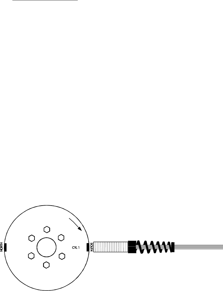
Typical setups (s1)
4 cylinder / 2 rotor engine
For a four cylinder 2 magnets are required in total, positioned exactly 180° apart.
Figure 1: Typical 4 Cylinder/ 2 Rotor Application