
Manual
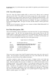
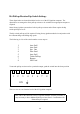

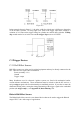
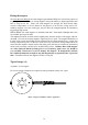
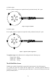
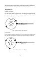
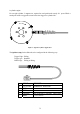
Table Of Contents
- Introduction
- SECTION 1 Getting Started
- CHAPTER 1 HALTECH IG5 INSTALLATION
- 1.1 Overview
- 1.2 Installation Summary
- 1.3 Expanded Installation Guide
- 1.3.1. Manifold Absolute Pressure (MAP) Sensor
- 1.3.2. Coolant Temperature Sensor
- 1.3.3. Inlet Air Temperature Sensor
- 1.3.4. The Throttle Position Sensor (TPS)
- 1.3.5. Mounting the Igniter
- 1.3.6. Route Wiring Harness and Connect Sensors
- 1.3.7. Power Relays
- 1.3.8. Electronic Control Unit (ECU)
- 1.3.9. Flying Leads
- 1.3.10. Install and connect any Optional Outputs
- 1.3.11 Connect the Trigger Sensor
- 1.3.12 Connect the ECU
- CHAPTER 2 GETTING ONLINE
- CHAPTER 3 ENGINE IDENTIFICATION
- CHAPTER 4 USING HALTECH SOFTWARE
- CHAPTER 5 STARTING THE ENGINE
- CHAPTER 1 HALTECH IG5 INSTALLATION
- SECTION 2 Other Adjustable Features
- SECTION 3 Software Features
- SECTION 4 IG5 Optional Outputs
- CHAPTER 12 SOFTWARE ACCESS
- CHAPTER 13 AUXILIARY OUTPUTS
- 13.1 Description
- 13.2 Turbo Waste Gate Control (TWG)
- 13.3 Dual Intake Valve Control (DIV)
- 13.4 Torque Converter Lockup (TCC)
- 13.5 Electric Thermatic Fan Control (TF)
- 13.6 Electric Intercooler Fan Control (IF)
- 13.7 Shift Light Illumination (SL)
- 13.8 Anti-Stall Solenoid Control (AS)
- 13.9 Turbo Timer (TT)
- 13.10 NOS Switch
- SECTION 5 Appendices

71
The most common application is in a direct fire configuration where a synchronisation event
is required. As the Haltech hall effect sensor is dual channel, it can provide this
synchronisation pulse as well as the trigger signal.
The principle behind its operation is quite simple. As a magnet passes the sensor the output
state changes from high to low. The orientation of the magnets determines the output signals
from the sensor.
There are two types of hall effect sensors available from Haltech
The S1 Hall Effect Sensor
The S1 sensor which is identified by a black cable gland, operates in the following way:
As a south pole passes the sensor face the signal in both the primary (PIN C) and secondary
(PIN D) channels are switched to a low state. As a north pole passes the sensor a low state
will only occur on the primary channel.
Note: magnets should always be mounted in a non ferrous material such as
aluminium.
With these characteristics a direct fire can be set up in the following way:
Using the sensor on the crank
After a suitable mounting location for the sensor has been found the engine should be
positioned at approximately 75° BTDC on cylinder no.1 compression. The magnet should
now be placed in the aluminium disk with the south pole facing towards the sensor, making
sure the magnet is in line with the sensor when the engine is in this position. This is now the
reference point for all the other magnets. The number of cylinders will determine the number
of magnets required and the angle of installation. The remainder of the magnets to be fitted
will all have a north pole facing the sensor.
The adjustment of the air gap will be determined by the strength of the magnets used. This
should be tested once the wheel assembly has been installed. Checking the Engine Data page
for steady RPM is usually a good indication that the airgap is acceptable.
Identifying the magnets poles
If you need to identify the magnet poles this can be done easily with the use of a multimeter.
By powering up the sensor, using 12 volts (PIN B) and ground (PIN A)
the secondary trigger channel (PIN D) can be checked to identify a south pole. Connecting the
multimeter between PIN D and ground, 12 volts should be present. When a South pole is
placed in front of the sensor this value will go to 0 volts.