
Manual
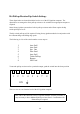

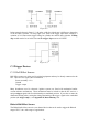
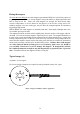
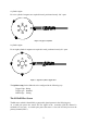
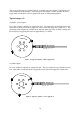
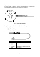
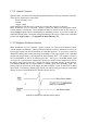
Table Of Contents
- Introduction
- SECTION 1 Getting Started
- CHAPTER 1 HALTECH IG5 INSTALLATION
- 1.1 Overview
- 1.2 Installation Summary
- 1.3 Expanded Installation Guide
- 1.3.1. Manifold Absolute Pressure (MAP) Sensor
- 1.3.2. Coolant Temperature Sensor
- 1.3.3. Inlet Air Temperature Sensor
- 1.3.4. The Throttle Position Sensor (TPS)
- 1.3.5. Mounting the Igniter
- 1.3.6. Route Wiring Harness and Connect Sensors
- 1.3.7. Power Relays
- 1.3.8. Electronic Control Unit (ECU)
- 1.3.9. Flying Leads
- 1.3.10. Install and connect any Optional Outputs
- 1.3.11 Connect the Trigger Sensor
- 1.3.12 Connect the ECU
- CHAPTER 2 GETTING ONLINE
- CHAPTER 3 ENGINE IDENTIFICATION
- CHAPTER 4 USING HALTECH SOFTWARE
- CHAPTER 5 STARTING THE ENGINE
- CHAPTER 1 HALTECH IG5 INSTALLATION
- SECTION 2 Other Adjustable Features
- SECTION 3 Software Features
- SECTION 4 IG5 Optional Outputs
- CHAPTER 12 SOFTWARE ACCESS
- CHAPTER 13 AUXILIARY OUTPUTS
- 13.1 Description
- 13.2 Turbo Waste Gate Control (TWG)
- 13.3 Dual Intake Valve Control (DIV)
- 13.4 Torque Converter Lockup (TCC)
- 13.5 Electric Thermatic Fan Control (TF)
- 13.6 Electric Intercooler Fan Control (IF)
- 13.7 Shift Light Illumination (SL)
- 13.8 Anti-Stall Solenoid Control (AS)
- 13.9 Turbo Timer (TT)
- 13.10 NOS Switch
- SECTION 5 Appendices
68
B.6 Pull-up Resistor Dip Switch Settings
These dipswitches are located inside the back cover of the IG5 ignition computer. The
dipswitches are arranged to allow pull-up resistors to be switched in to appropriate outputs as
required.
Some factory ignition systems have built in pull-up resistors and will not require the dip
switch pull-ups to be set.
The dip switch pull-ups will be required if using factory ignition modules in conjunction with
the constant charge and falling edge spark.
The following is a list of the switch number versus output :-
1 Aux Out2
2 Aux Out1
3 Ign. Out
4 Aux Out4
5 Aux Out3
6 Tacho Pull-up
7 Bypass
8 Not Used
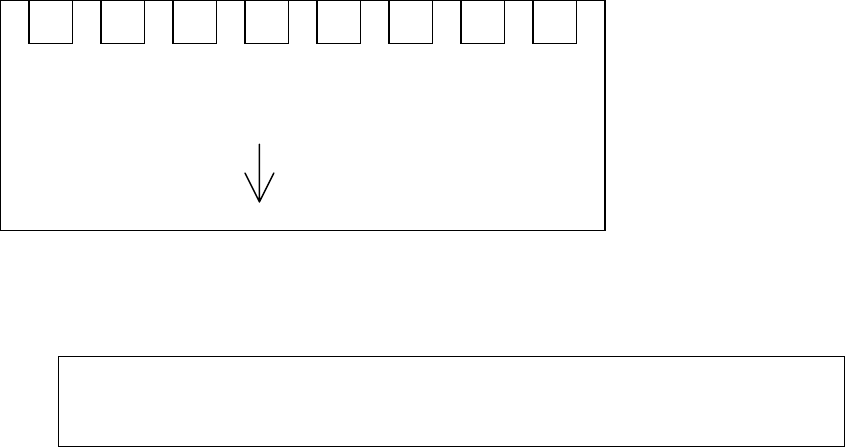
To turn the pull-up resistor on for a particular output, push the switch into the down position
This is a view as seen from the back of the IG5 ignition computer.
Note: Due to the enormous variety of ignition modules currently available, It
may necessary to have additional pull-up resistors fitted. Consultation with
Haltech may be required.
1 2 3 4 5 6 7 8
ON