
Manual
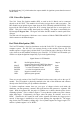
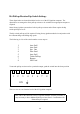

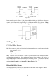
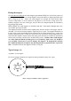
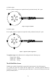
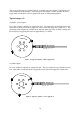
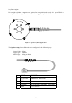
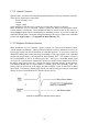
Table Of Contents
- Introduction
- SECTION 1 Getting Started
- CHAPTER 1 HALTECH IG5 INSTALLATION
- 1.1 Overview
- 1.2 Installation Summary
- 1.3 Expanded Installation Guide
- 1.3.1. Manifold Absolute Pressure (MAP) Sensor
- 1.3.2. Coolant Temperature Sensor
- 1.3.3. Inlet Air Temperature Sensor
- 1.3.4. The Throttle Position Sensor (TPS)
- 1.3.5. Mounting the Igniter
- 1.3.6. Route Wiring Harness and Connect Sensors
- 1.3.7. Power Relays
- 1.3.8. Electronic Control Unit (ECU)
- 1.3.9. Flying Leads
- 1.3.10. Install and connect any Optional Outputs
- 1.3.11 Connect the Trigger Sensor
- 1.3.12 Connect the ECU
- CHAPTER 2 GETTING ONLINE
- CHAPTER 3 ENGINE IDENTIFICATION
- CHAPTER 4 USING HALTECH SOFTWARE
- CHAPTER 5 STARTING THE ENGINE
- CHAPTER 1 HALTECH IG5 INSTALLATION
- SECTION 2 Other Adjustable Features
- SECTION 3 Software Features
- SECTION 4 IG5 Optional Outputs
- CHAPTER 12 SOFTWARE ACCESS
- CHAPTER 13 AUXILIARY OUTPUTS
- 13.1 Description
- 13.2 Turbo Waste Gate Control (TWG)
- 13.3 Dual Intake Valve Control (DIV)
- 13.4 Torque Converter Lockup (TCC)
- 13.5 Electric Thermatic Fan Control (TF)
- 13.6 Electric Intercooler Fan Control (IF)
- 13.7 Shift Light Illumination (SL)
- 13.8 Anti-Stall Solenoid Control (AS)
- 13.9 Turbo Timer (TT)
- 13.10 NOS Switch
- SECTION 5 Appendices
67
the Ignition Setup [3.2], which makes the output suitable for ignition systems that do not need
dwell control.
G.M. Direct Fire Ignition
The G.M. Direct Fire Ignition module (DFI), as used in the V6 Buick, can be connected
directly to the IG5 ECU. This module serves both as a trigger device and as an igniter. The
DFI module has an ignition bypass input from the ECU (Normally labelled BYPASS). This
input tells the DFI module to ignore the ECU’s timing signal and fire its own spark at 10°
BTDC. This gives a more reliably timed spark for cranking. This input is controlled by the
IG5 through the Bypass Line. The bypass will allow the DFI module to control spark below
450 rpm
The GM unit will incorporate a Reference out to connect to Haltech TRIGGER and EST IN
which connects to the Haltech output.
Ford Thick Film Ignition (TFI)
The Ford TFI module is fitted to distributors used with Ford’s EEC IV engine management
computer system. The IG5 ECU can connect directly to this module, however, the TFI
module requires a trigger signal, call the SPOUT (see following page), that has a 50/50 duty
cycle, which is not the standard 70/30 duty cycle of the IG5. To use the Ford TFI module you
will have to adjust the Ignition Output Duty Cycle in the Ignition Setup.
Signal Names for TFI Module
PIP Profile Ignition Pick up Output
(trigger pulses from the Hall Effect Sensor)
SPOUT Spark Out (Igniter output from the ECU) Input
POWER + 12 volts from starter circuit Input
POWER + 12 volts from ignition switch Input
COIL - Negative terminal of coil Output
GND Ignition system ground
There are several versions of the Ford TFI module but these notes only refer to the type IV
module. This TFI module is physically attached to the side of the distributor and connects
directly to the HALL Effect pick up within the distributor.
To further complicate matters there are two types of chopper wheels used inside the
distributor, one that generates a normal’ PIP signal and one that generates a ‘signature’ PIP
signal. With the signature PIP, the pulse for cylinder one is shorter than the pulses for the
remaining cylinders. This is similar to Figure C.3 except that the cylinder one pulse is shorter
rather than longer. Unfortunately, the edges where the pulses do coincide, occur at 10°
BTDC. Therefore the IG5 cannot be used with a signature PIP unless the trigger point is
moved. If the trigger is modified be wary of rotor phasing (See Appendix D). The trigger
edge for the Ford TFI module is falling edge. For 8 cylinder engines the Trigger Angle is 55°
and for 6 cylinder engines it is 70° BTDC.