
Manual
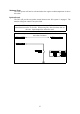
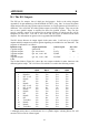
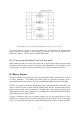
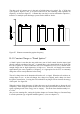
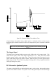
Table Of Contents
- Introduction
- SECTION 1 Getting Started
- CHAPTER 1 HALTECH IG5 INSTALLATION
- 1.1 Overview
- 1.2 Installation Summary
- 1.3 Expanded Installation Guide
- 1.3.1. Manifold Absolute Pressure (MAP) Sensor
- 1.3.2. Coolant Temperature Sensor
- 1.3.3. Inlet Air Temperature Sensor
- 1.3.4. The Throttle Position Sensor (TPS)
- 1.3.5. Mounting the Igniter
- 1.3.6. Route Wiring Harness and Connect Sensors
- 1.3.7. Power Relays
- 1.3.8. Electronic Control Unit (ECU)
- 1.3.9. Flying Leads
- 1.3.10. Install and connect any Optional Outputs
- 1.3.11 Connect the Trigger Sensor
- 1.3.12 Connect the ECU
- CHAPTER 2 GETTING ONLINE
- CHAPTER 3 ENGINE IDENTIFICATION
- CHAPTER 4 USING HALTECH SOFTWARE
- CHAPTER 5 STARTING THE ENGINE
- CHAPTER 1 HALTECH IG5 INSTALLATION
- SECTION 2 Other Adjustable Features
- SECTION 3 Software Features
- SECTION 4 IG5 Optional Outputs
- CHAPTER 12 SOFTWARE ACCESS
- CHAPTER 13 AUXILIARY OUTPUTS
- 13.1 Description
- 13.2 Turbo Waste Gate Control (TWG)
- 13.3 Dual Intake Valve Control (DIV)
- 13.4 Torque Converter Lockup (TCC)
- 13.5 Electric Thermatic Fan Control (TF)
- 13.6 Electric Intercooler Fan Control (IF)
- 13.7 Shift Light Illumination (SL)
- 13.8 Anti-Stall Solenoid Control (AS)
- 13.9 Turbo Timer (TT)
- 13.10 NOS Switch
- SECTION 5 Appendices
65
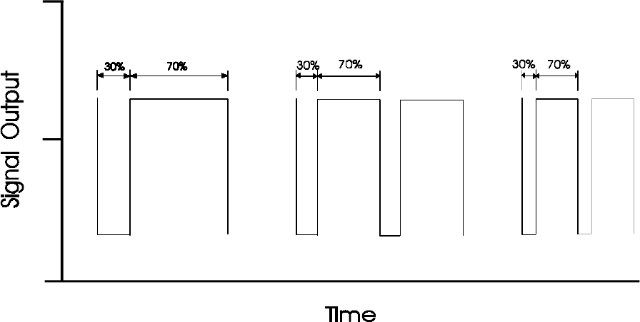
The duty cycle of a square wave is the ratio of its high time to its period. Eg. a 70/30 duty
cycle signal is high for 70% of its period and low for the remaining 30% regardless of
frequency, as shown in figure E7. Constant duty can also be used on aftermarket capacitive-,
inductive- or multiple-spark discharge systems such as MSD or Jacobs.
Figure E7. Illustrate constant duty against frequency
B 4.1 Constant Charge or “Dumb Igniters”
A "dumb" igniter is one that does not perform any sort of dwell control, thus the input signal
directly controls switching of the coil. A constant duty cycle signal should not be used with
this sort of igniter as it will overheat the coil at low frequencies (ie low revs), and not allow
enough charge time at high frequencies (ie high revs). Since the coil charge time remains
approximately the same regardless of frequency, it is appropriate for the ECU to constantly
charge the coil for exactly that time before firing.
The coil’s charge time can be determined from the coil -ve signal. When the coil switches on,
voltage drops to zero. As the coil charges, the voltage rises slightly, until a sharp rise where
the igniter current limits. Leaving the coil switched on any longer will not increase the energy
of the spark. See figure E8.
When the ignition firing frequency is high, there may not be enough time to charge the coil
completely. After firing the spark, the IG5 waits for a short period, then switches the coil on
again, regaining much of the energy lost in “ringing”. This break time should normally be 1
to 1.5ms.
(See previous warnings Re: setting the Ignition Output to Constant Charge or Constant Duty
to suit the particular type of ignition module (igniter). (Also see chapter 3.2).