
Manual
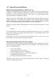
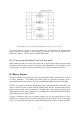
Table Of Contents
- Introduction
- SECTION 1 Getting Started
- CHAPTER 1 HALTECH IG5 INSTALLATION
- 1.1 Overview
- 1.2 Installation Summary
- 1.3 Expanded Installation Guide
- 1.3.1. Manifold Absolute Pressure (MAP) Sensor
- 1.3.2. Coolant Temperature Sensor
- 1.3.3. Inlet Air Temperature Sensor
- 1.3.4. The Throttle Position Sensor (TPS)
- 1.3.5. Mounting the Igniter
- 1.3.6. Route Wiring Harness and Connect Sensors
- 1.3.7. Power Relays
- 1.3.8. Electronic Control Unit (ECU)
- 1.3.9. Flying Leads
- 1.3.10. Install and connect any Optional Outputs
- 1.3.11 Connect the Trigger Sensor
- 1.3.12 Connect the ECU
- CHAPTER 2 GETTING ONLINE
- CHAPTER 3 ENGINE IDENTIFICATION
- CHAPTER 4 USING HALTECH SOFTWARE
- CHAPTER 5 STARTING THE ENGINE
- CHAPTER 1 HALTECH IG5 INSTALLATION
- SECTION 2 Other Adjustable Features
- SECTION 3 Software Features
- SECTION 4 IG5 Optional Outputs
- CHAPTER 12 SOFTWARE ACCESS
- CHAPTER 13 AUXILIARY OUTPUTS
- 13.1 Description
- 13.2 Turbo Waste Gate Control (TWG)
- 13.3 Dual Intake Valve Control (DIV)
- 13.4 Torque Converter Lockup (TCC)
- 13.5 Electric Thermatic Fan Control (TF)
- 13.6 Electric Intercooler Fan Control (IF)
- 13.7 Shift Light Illumination (SL)
- 13.8 Anti-Stall Solenoid Control (AS)
- 13.9 Turbo Timer (TT)
- 13.10 NOS Switch
- SECTION 5 Appendices
63
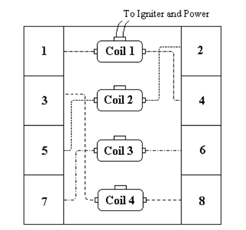
Figure B2.2. Coil layout for V8 with firing order 1, 2, 7, 8, 4, 5, 6, 3.
It is not necessary for coil one to connect to cylinder one. If, for instance, the original Home
trigger occurs before cylinder 6 (not common, but possible) then coil one would need to
connect to cylinder 6. The coil order would still be the same.
B.2.3 Converting Individual Coils to Waste Spark
Single ended coils can be used for waste spark with a single ignition output signal activating
two igniters which in turn would fire two ignition coils simultaneously. For example, on a six
cylinder engine, six igniters would be required but only 3 ignition signals from the IG5.
B.3 Rotary Engines
The IG5 is capable of providing spark to twin-rotor Wankel engines, both in direct fire form
or with a distributor. The leading and trailing sparks are generated separately, with a
programmable split between them. The split is programd through the Rotary Trailing Map.
There are two ranges to the Rotary Trailing Map, below 2000 rpm and above 2000 rpm. This
map is a measure of split, or delay, from the leading spark, which is computed from the base
ignition map normally with all corrections. The map indexes split against the engine load.
When displayed on the Engine Data Page, or in datalogs, the trailing spark timing is shown as
an absolute advance in degrees BTDC.
If using a distributor, there are two ignition outputs, one for the leading and one for the
trailing coils. If using direct fire, the two leading sparks are fired together, as in a waste-spark
set-up. Two individual coils must be used for the trailing sparks, as these are fired separately.