
Manual
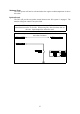
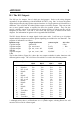
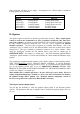
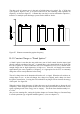
Table Of Contents
- Introduction
- SECTION 1 Getting Started
- CHAPTER 1 HALTECH IG5 INSTALLATION
- 1.1 Overview
- 1.2 Installation Summary
- 1.3 Expanded Installation Guide
- 1.3.1. Manifold Absolute Pressure (MAP) Sensor
- 1.3.2. Coolant Temperature Sensor
- 1.3.3. Inlet Air Temperature Sensor
- 1.3.4. The Throttle Position Sensor (TPS)
- 1.3.5. Mounting the Igniter
- 1.3.6. Route Wiring Harness and Connect Sensors
- 1.3.7. Power Relays
- 1.3.8. Electronic Control Unit (ECU)
- 1.3.9. Flying Leads
- 1.3.10. Install and connect any Optional Outputs
- 1.3.11 Connect the Trigger Sensor
- 1.3.12 Connect the ECU
- CHAPTER 2 GETTING ONLINE
- CHAPTER 3 ENGINE IDENTIFICATION
- CHAPTER 4 USING HALTECH SOFTWARE
- CHAPTER 5 STARTING THE ENGINE
- CHAPTER 1 HALTECH IG5 INSTALLATION
- SECTION 2 Other Adjustable Features
- SECTION 3 Software Features
- SECTION 4 IG5 Optional Outputs
- CHAPTER 12 SOFTWARE ACCESS
- CHAPTER 13 AUXILIARY OUTPUTS
- 13.1 Description
- 13.2 Turbo Waste Gate Control (TWG)
- 13.3 Dual Intake Valve Control (DIV)
- 13.4 Torque Converter Lockup (TCC)
- 13.5 Electric Thermatic Fan Control (TF)
- 13.6 Electric Intercooler Fan Control (IF)
- 13.7 Shift Light Illumination (SL)
- 13.8 Anti-Stall Solenoid Control (AS)
- 13.9 Turbo Timer (TT)
- 13.10 NOS Switch
- SECTION 5 Appendices

61
APPENDIX B
B.1 The IG5 Outputs
The IG5 has five outputs, four of which are dual purpose. Refer to the wiring diagram
Appendix E for pin numbering of the IGNITION OUTPUT plug. Pin C is always an ignition
output and provides the only ignition output when there is a single ignition coil connected to a
distributor. Pins A,D,E &F are either ignition outputs or auxiliary outputs. They can provide
one or more ignition outputs as required for direct fire ignition systems. They can also
provide auxiliary outputs if not required for an ignition function in which case they will be
designated as Aux Out 1, Aux Out 2, Aux Out 3 and Aux Out 4 as marked on the loom
diagram. For information on igniters refer to appendix B4 IGNITERS.
The IG5 always allocates its output signals in the same order. It will use up to 4 ignition
outputs and those outputs not used for ignition signalling are available for Aux functions. The
sequence of utilisation is as follows.
Ignition set-up output signal name connector pins wire color
1 ignition output ignition out C L.Grn
2 ignition outputs ign. out & Aux 1 C & D “ Blu
3 ignition outputs ign. out , Aux 1 & 2 C,D&E “ “
Wht/Blk
4 ignition outputs ign. out , Aux 1,2 &3 C,D,E&F “ “ “
L.Blu
The list that follows (Figure B.1) shows the Aux outputs available for other functions with
different ignition setups. DF is for Direct Fire which is covered in the following section.
# Cyl. Ignition Aux
Out1
Aux.
Out 2
Aux
Out 3
Aux
Out4
1 Distrib* Yes Yes Yes Yes
2 Distrib** Yes Yes Yes Yes
2 DF - 2 coil No Yes Yes Yes
3 Distrib Yes Yes Yes Yes
3 DF No No Yes Yes
4 Distrib Yes Yes Yes Yes
4 DF - 2 coil No Yes Yes Yes
4 DF - 4 coil No No No Yes
5 Distrib Yes Yes Yes Yes
6 Distrib Yes Yes Yes Yes
6 DF No No Yes Yes
8 Distrib Yes Yes Yes Yes
8 DF No No No Yes
8 Twin Dist No Yes Yes Yes
10 Distrib Yes Yes Yes Yes
12 Distrib Yes Yes Yes Yes
12 Twin Dist No Yes Yes Yes
Figure B.1. Aux. Out applications.
* Although strictly there is no distributor on a 1 cylinder engine, selecting Direct Fire will
cause the IG5 to wait for a Home signal.