
Manual
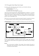
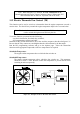
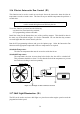
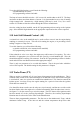
Table Of Contents
- Introduction
- SECTION 1 Getting Started
- CHAPTER 1 HALTECH IG5 INSTALLATION
- 1.1 Overview
- 1.2 Installation Summary
- 1.3 Expanded Installation Guide
- 1.3.1. Manifold Absolute Pressure (MAP) Sensor
- 1.3.2. Coolant Temperature Sensor
- 1.3.3. Inlet Air Temperature Sensor
- 1.3.4. The Throttle Position Sensor (TPS)
- 1.3.5. Mounting the Igniter
- 1.3.6. Route Wiring Harness and Connect Sensors
- 1.3.7. Power Relays
- 1.3.8. Electronic Control Unit (ECU)
- 1.3.9. Flying Leads
- 1.3.10. Install and connect any Optional Outputs
- 1.3.11 Connect the Trigger Sensor
- 1.3.12 Connect the ECU
- CHAPTER 2 GETTING ONLINE
- CHAPTER 3 ENGINE IDENTIFICATION
- CHAPTER 4 USING HALTECH SOFTWARE
- CHAPTER 5 STARTING THE ENGINE
- CHAPTER 1 HALTECH IG5 INSTALLATION
- SECTION 2 Other Adjustable Features
- SECTION 3 Software Features
- SECTION 4 IG5 Optional Outputs
- CHAPTER 12 SOFTWARE ACCESS
- CHAPTER 13 AUXILIARY OUTPUTS
- 13.1 Description
- 13.2 Turbo Waste Gate Control (TWG)
- 13.3 Dual Intake Valve Control (DIV)
- 13.4 Torque Converter Lockup (TCC)
- 13.5 Electric Thermatic Fan Control (TF)
- 13.6 Electric Intercooler Fan Control (IF)
- 13.7 Shift Light Illumination (SL)
- 13.8 Anti-Stall Solenoid Control (AS)
- 13.9 Turbo Timer (TT)
- 13.10 NOS Switch
- SECTION 5 Appendices
56
respective values, the output will switch off. The last parameter is the Run Time. This is the
maximum time the ECU will allow the engine to continue to run after the ignition switch has
been turned off. If either of the temperature conditions are meet before this time, the output
(and therefore, the engine) will switch off. The Run Time is set to the nearest half minute.
Figure 17.6 – Turbo Timer diagram
Note: When using the Turbo Timer function, the Aux. In Function in the
Identification must be set for Turbo Timer. When using TT, other functions
that use the Aux. Input/Output line can not be used.
13.10 NOS Switch
This function controls the operation of a NOS system. It does not control the delivery of the
Nitrous Oxide, but simply turns the system on or off in certain conditions. The Nos system
must control the delivery of the nitrous oxide and must also provide extra fuel delivery. The
output is enabled by a switch connected to the Auxiliary Input/Output. Once enabled, if the
conditions stated below are met, the NOS system will be activated. The Auxiliary
Input/Output Function in the Identification must be set to NOS Switch for the function to
operate correctly.
There are five adjustable parameters :
Load Bar
If the Ignition Map Bar Number exceeds this value, the NOS system will be turned off.
This is used for turbo engines where the Nos is used to help boost the turbo. Once on
boost, the Nos can be turned off. Normally aspirated engines, on the other hand, can
use Nos at full load, so this value should be set to bar 32.
Max. Rpm
If the Rpm exceeds this value, the NOS system will be switched off.
Min. Rpm
If the Rpm is below this value the NOS system will not be activated.
Minimum Throttle
The NOS system will be turned on above this value.