
Manual
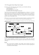
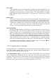
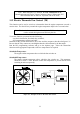
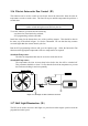
Table Of Contents
- Introduction
- SECTION 1 Getting Started
- CHAPTER 1 HALTECH IG5 INSTALLATION
- 1.1 Overview
- 1.2 Installation Summary
- 1.3 Expanded Installation Guide
- 1.3.1. Manifold Absolute Pressure (MAP) Sensor
- 1.3.2. Coolant Temperature Sensor
- 1.3.3. Inlet Air Temperature Sensor
- 1.3.4. The Throttle Position Sensor (TPS)
- 1.3.5. Mounting the Igniter
- 1.3.6. Route Wiring Harness and Connect Sensors
- 1.3.7. Power Relays
- 1.3.8. Electronic Control Unit (ECU)
- 1.3.9. Flying Leads
- 1.3.10. Install and connect any Optional Outputs
- 1.3.11 Connect the Trigger Sensor
- 1.3.12 Connect the ECU
- CHAPTER 2 GETTING ONLINE
- CHAPTER 3 ENGINE IDENTIFICATION
- CHAPTER 4 USING HALTECH SOFTWARE
- CHAPTER 5 STARTING THE ENGINE
- CHAPTER 1 HALTECH IG5 INSTALLATION
- SECTION 2 Other Adjustable Features
- SECTION 3 Software Features
- SECTION 4 IG5 Optional Outputs
- CHAPTER 12 SOFTWARE ACCESS
- CHAPTER 13 AUXILIARY OUTPUTS
- 13.1 Description
- 13.2 Turbo Waste Gate Control (TWG)
- 13.3 Dual Intake Valve Control (DIV)
- 13.4 Torque Converter Lockup (TCC)
- 13.5 Electric Thermatic Fan Control (TF)
- 13.6 Electric Intercooler Fan Control (IF)
- 13.7 Shift Light Illumination (SL)
- 13.8 Anti-Stall Solenoid Control (AS)
- 13.9 Turbo Timer (TT)
- 13.10 NOS Switch
- SECTION 5 Appendices
54
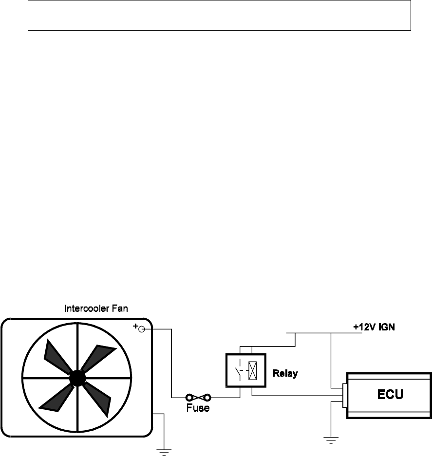
13.6 Electric Intercooler Fan Control (IF)
This function can be used to switch on an electric fan on the intercooler when the inlet air
temperature exceeds a certain value. The fan will stay on until the temperature drops below a
second value.
Note: The electric fan cannot be driven directly by the ECU. A relay must be
used to switch the high currents drawn by the fan.
To use this function, you must have the following:
- an electric fan, fused and relay switched;
- IG5 programming software and cable.
Install the wiring for the thermofan to one of the Auxiliary outputs. This should be done in
the same way as described in figure 13.6 for the Thermofan. Be sure that the relay contacts
are rated higher than the current drawn by the fan.
Run the IG5 programming software and go to the Options page. Select the Intercooler Fan
function on the appropriate output and set the two temperatures as required.
Switch On Temperature
The inlet air temperature that must be exceed to switch the fan on.
Switch Off Temperature
The temperature the inlet air must drop below before the fan will be switched off.
This parameter should be at least 5° lower than the Switch On temperature to prevent
the fan from switching in and out repeatedly.
Figure 13.6. Example circuit for an Intercooler Fan.
13.7 Shift Light Illumination (SL)
The IG5 can be used to activate a shift light or a piezo buzzer when engine speed exceeds the
programd activation speed.