
Manual
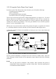
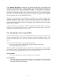
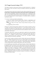
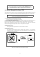
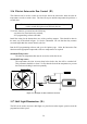
Table Of Contents
- Introduction
- SECTION 1 Getting Started
- CHAPTER 1 HALTECH IG5 INSTALLATION
- 1.1 Overview
- 1.2 Installation Summary
- 1.3 Expanded Installation Guide
- 1.3.1. Manifold Absolute Pressure (MAP) Sensor
- 1.3.2. Coolant Temperature Sensor
- 1.3.3. Inlet Air Temperature Sensor
- 1.3.4. The Throttle Position Sensor (TPS)
- 1.3.5. Mounting the Igniter
- 1.3.6. Route Wiring Harness and Connect Sensors
- 1.3.7. Power Relays
- 1.3.8. Electronic Control Unit (ECU)
- 1.3.9. Flying Leads
- 1.3.10. Install and connect any Optional Outputs
- 1.3.11 Connect the Trigger Sensor
- 1.3.12 Connect the ECU
- CHAPTER 2 GETTING ONLINE
- CHAPTER 3 ENGINE IDENTIFICATION
- CHAPTER 4 USING HALTECH SOFTWARE
- CHAPTER 5 STARTING THE ENGINE
- CHAPTER 1 HALTECH IG5 INSTALLATION
- SECTION 2 Other Adjustable Features
- SECTION 3 Software Features
- SECTION 4 IG5 Optional Outputs
- CHAPTER 12 SOFTWARE ACCESS
- CHAPTER 13 AUXILIARY OUTPUTS
- 13.1 Description
- 13.2 Turbo Waste Gate Control (TWG)
- 13.3 Dual Intake Valve Control (DIV)
- 13.4 Torque Converter Lockup (TCC)
- 13.5 Electric Thermatic Fan Control (TF)
- 13.6 Electric Intercooler Fan Control (IF)
- 13.7 Shift Light Illumination (SL)
- 13.8 Anti-Stall Solenoid Control (AS)
- 13.9 Turbo Timer (TT)
- 13.10 NOS Switch
- SECTION 5 Appendices
49
13.2.2 Using the Turbo Waste Gate Control
In order to use the Turbo Waste Gate Control function, you will need the following:
- a suitable pressure solenoid valve;
- air hose and fittings;
- IG5 programming software and cable;
- an overboost relief valve (strongly recommended).
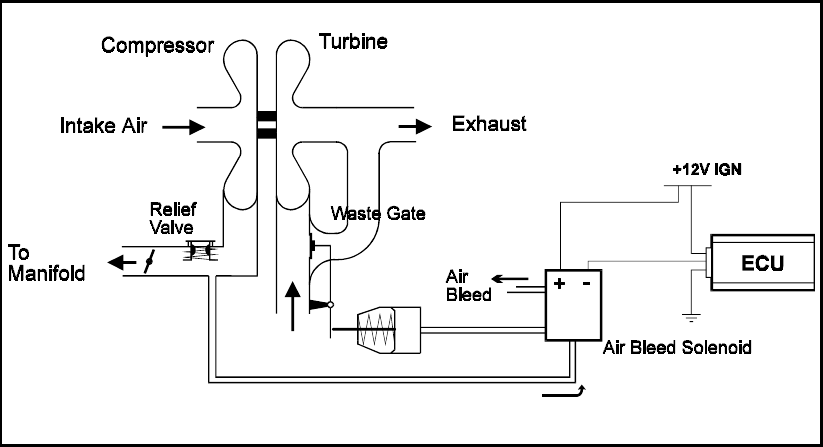
The air circuit to the waste gate must be configured appropriately, as in figure 16.1. If it is not
directly filtered, the air bleed line to the solenoid should run to the air box or into the car
body, free from road dust. Install the solenoid valve securely, and power and signal from the
Auxiliary I/O connector on the harness. The waste gate should be re-set so that its operation
point is very low, around 20kPa (3 psi).
NB: Be sure to use air hose that is rated to the pressure the engine is expected to be boosted
to. All fittings should be secured so that they will not disconnect under high pressures.
A relief valve should be fitted to the manifold as a backup in case of an air hose failure and
uncontrolled boost.
Figure 13.2. Diagram of Turbo with Wastegate Control Solenoid.
Once the solenoid installation is complete run the IG5 software in Online mode. Select the
Turbo Wastegate Control Function on the appropriate output channel, and set the following
parameters.
Period
This sets the period of oscillation of the solenoid. Most solenoids will operate at
around 30Hz, which corresponds to a period of about 30ms. Enter the required period
of oscillation in milliseconds here.