
Manual
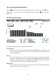
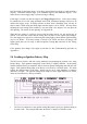
Table Of Contents
- Introduction
- SECTION 1 Getting Started
- CHAPTER 1 HALTECH IG5 INSTALLATION
- 1.1 Overview
- 1.2 Installation Summary
- 1.3 Expanded Installation Guide
- 1.3.1. Manifold Absolute Pressure (MAP) Sensor
- 1.3.2. Coolant Temperature Sensor
- 1.3.3. Inlet Air Temperature Sensor
- 1.3.4. The Throttle Position Sensor (TPS)
- 1.3.5. Mounting the Igniter
- 1.3.6. Route Wiring Harness and Connect Sensors
- 1.3.7. Power Relays
- 1.3.8. Electronic Control Unit (ECU)
- 1.3.9. Flying Leads
- 1.3.10. Install and connect any Optional Outputs
- 1.3.11 Connect the Trigger Sensor
- 1.3.12 Connect the ECU
- CHAPTER 2 GETTING ONLINE
- CHAPTER 3 ENGINE IDENTIFICATION
- CHAPTER 4 USING HALTECH SOFTWARE
- CHAPTER 5 STARTING THE ENGINE
- CHAPTER 1 HALTECH IG5 INSTALLATION
- SECTION 2 Other Adjustable Features
- SECTION 3 Software Features
- SECTION 4 IG5 Optional Outputs
- CHAPTER 12 SOFTWARE ACCESS
- CHAPTER 13 AUXILIARY OUTPUTS
- 13.1 Description
- 13.2 Turbo Waste Gate Control (TWG)
- 13.3 Dual Intake Valve Control (DIV)
- 13.4 Torque Converter Lockup (TCC)
- 13.5 Electric Thermatic Fan Control (TF)
- 13.6 Electric Intercooler Fan Control (IF)
- 13.7 Shift Light Illumination (SL)
- 13.8 Anti-Stall Solenoid Control (AS)
- 13.9 Turbo Timer (TT)
- 13.10 NOS Switch
- SECTION 5 Appendices
30
the All Ranges option for a starting point, press
ƒρ
ƒρƒρ
ƒρ
once more to exit the All Ranges option
and tailor each map individually.
This option is only available on the Base Ignition Maps.
4.8.3 Selecting Groups of Bars
Groups of adjacent bars may be highlighted and adjusted together.
Hold
♣
♣♣
♣
while using the left or right arrow keys,
∞
∞∞
∞
⁄
⁄⁄
⁄
, and you will highlight a group of bars.
This group will now act in unison when increasing or decreasing the height of the Bars. To
deselect the highlighted Bars use the
ƒ
ƒƒ
ƒ
and arrow keys together.
4.8.4 Percentage Changes
Using this function will prompt you to enter a percentage change to the selected bars. An
entry of "20" will increase each bar by 20%, while an entry of "-15" will decrease the bars by
15%. This change only affects the highlighted bar(s).
4.8.5 Linearise
When a group of bars is selected (more than two), this function can be used to set the values
between the end points. Highlight the bars between two load points that are known to be
correct and press
ƒλ
ƒλƒλ
ƒλ
. The programming software will automatically adjust all the bars
between the two end points to form a straight line. This feature facilitates fast programming
and the smoothing of maps.
4.8.6 Numeric Mode
This will take you into numerical mode, displaying the map as a spreadsheet. This mode is
available if wanted, but graphical mapping is recommended as it is much easier to use. To
exit from Numeric Mode and go back to using the maps press the
°
°°
°
key.
4.8.7 Bar Increments
The Up and Down arrows,
≤
≤≤
≤
′
′′
′
, normally change the bar height in the maps by a pre-
determined amount, usually the smallest possible increment. PgUp and PgDn also change the
bars by a pre-determined amount. These increments (the value of the keystroke) can be
changed by the user.
ƒι
ƒιƒι
ƒι
will bring you to a screen where the increments associated with
particular keys can be changed.