
Manual
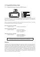
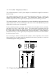
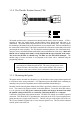
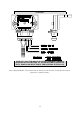
Table Of Contents
- Introduction
- SECTION 1 Getting Started
- CHAPTER 1 HALTECH IG5 INSTALLATION
- 1.1 Overview
- 1.2 Installation Summary
- 1.3 Expanded Installation Guide
- 1.3.1. Manifold Absolute Pressure (MAP) Sensor
- 1.3.2. Coolant Temperature Sensor
- 1.3.3. Inlet Air Temperature Sensor
- 1.3.4. The Throttle Position Sensor (TPS)
- 1.3.5. Mounting the Igniter
- 1.3.6. Route Wiring Harness and Connect Sensors
- 1.3.7. Power Relays
- 1.3.8. Electronic Control Unit (ECU)
- 1.3.9. Flying Leads
- 1.3.10. Install and connect any Optional Outputs
- 1.3.11 Connect the Trigger Sensor
- 1.3.12 Connect the ECU
- CHAPTER 2 GETTING ONLINE
- CHAPTER 3 ENGINE IDENTIFICATION
- CHAPTER 4 USING HALTECH SOFTWARE
- CHAPTER 5 STARTING THE ENGINE
- CHAPTER 1 HALTECH IG5 INSTALLATION
- SECTION 2 Other Adjustable Features
- SECTION 3 Software Features
- SECTION 4 IG5 Optional Outputs
- CHAPTER 12 SOFTWARE ACCESS
- CHAPTER 13 AUXILIARY OUTPUTS
- 13.1 Description
- 13.2 Turbo Waste Gate Control (TWG)
- 13.3 Dual Intake Valve Control (DIV)
- 13.4 Torque Converter Lockup (TCC)
- 13.5 Electric Thermatic Fan Control (TF)
- 13.6 Electric Intercooler Fan Control (IF)
- 13.7 Shift Light Illumination (SL)
- 13.8 Anti-Stall Solenoid Control (AS)
- 13.9 Turbo Timer (TT)
- 13.10 NOS Switch
- SECTION 5 Appendices
14
1.3.6. Route Wiring Harness and Connect Sensors
Lay the main wiring harness out in the engine bay with the sensors mounted to ascertain the
best fit for the harness. Pass the wiring loom through a hole in the engine bay firewall and
into the passenger compartment where the ECU will be mounted. Either use an existing hole
or cut a new hole to suit. Use a rubber grommet or similar device to protect the harness from
being damaged by rubbing on the sharp edge of the hole.
WARNING:
DO NOT ALLOW THE HARNESS TO TOUCH HOT EXHAUST
PARTS INCLUDING MANIFOLDS OR TURBOCHARGER'S.
TRY TO ROUTE THE MAIN HARNESS AWAY FROM HIGH
VOLTAGE IGNITION LEADS. UNDER NO CIRCUMSTANCES RUN
ANY WIRING PARALLEL TO OR IN CONTACT WITH THE
IGNITION LEADS.
Note: Be neat. Run the harness in a tidy fashion. Try to run the harness along
paths used by original wiring. Use nylon cable ties to secure the harness in
place, but do not stress the wiring or connectors.
Once the harness is fitted, connect all the sensors to their appropriate plugs.
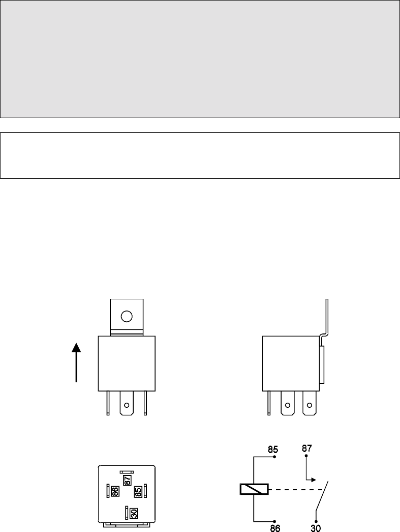
1.3.7. Power Relays
There is one relay used with the Haltech IG5, (the Main Power Relay)
It should be mounted on the firewall or an inner guard with the connector terminals to the
bottom as shown in the diagram.