
Manual
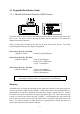
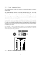
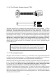
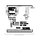
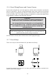
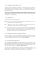
Table Of Contents
- Introduction
- SECTION 1 Getting Started
- CHAPTER 1 HALTECH IG5 INSTALLATION
- 1.1 Overview
- 1.2 Installation Summary
- 1.3 Expanded Installation Guide
- 1.3.1. Manifold Absolute Pressure (MAP) Sensor
- 1.3.2. Coolant Temperature Sensor
- 1.3.3. Inlet Air Temperature Sensor
- 1.3.4. The Throttle Position Sensor (TPS)
- 1.3.5. Mounting the Igniter
- 1.3.6. Route Wiring Harness and Connect Sensors
- 1.3.7. Power Relays
- 1.3.8. Electronic Control Unit (ECU)
- 1.3.9. Flying Leads
- 1.3.10. Install and connect any Optional Outputs
- 1.3.11 Connect the Trigger Sensor
- 1.3.12 Connect the ECU
- CHAPTER 2 GETTING ONLINE
- CHAPTER 3 ENGINE IDENTIFICATION
- CHAPTER 4 USING HALTECH SOFTWARE
- CHAPTER 5 STARTING THE ENGINE
- CHAPTER 1 HALTECH IG5 INSTALLATION
- SECTION 2 Other Adjustable Features
- SECTION 3 Software Features
- SECTION 4 IG5 Optional Outputs
- CHAPTER 12 SOFTWARE ACCESS
- CHAPTER 13 AUXILIARY OUTPUTS
- 13.1 Description
- 13.2 Turbo Waste Gate Control (TWG)
- 13.3 Dual Intake Valve Control (DIV)
- 13.4 Torque Converter Lockup (TCC)
- 13.5 Electric Thermatic Fan Control (TF)
- 13.6 Electric Intercooler Fan Control (IF)
- 13.7 Shift Light Illumination (SL)
- 13.8 Anti-Stall Solenoid Control (AS)
- 13.9 Turbo Timer (TT)
- 13.10 NOS Switch
- SECTION 5 Appendices
9
1.3 Expanded Installation Guide
1.3.1. Manifold Absolute Pressure (MAP) Sensor
The MAP sensor is used to convert the manifold pressure into an electrical signal for the IG5
ECU to use. The sensor works in absolute pressures, thus its calibration is not affected by
changes in barometric pressure.
There are three types of MAP sensors that can be used with the IG5 system. The sensor
required depends on the specific engine configuration.
1 Bar Sensor (Part No. 039 4070)
( -100kPa to 0 kPa) Normally Aspirated Engines
2 Bar Sensor (Part No. 886 3189)
(-100kPa to 100kPa) Turbo or Supercharged
Engines up to 100kPa boost
(15 psi , 1 atmosphere)
3 Bar Sensor (Part No. 749 3169)
(-100kPa to 200kPa) Turbo or Supercharged
Engines up to 200kPa boost
(30 Psi, 2 atmospheres)
Note: Make sure you have the correct MAP sensor for your engine. The first
three digits of the part number is stamped on the sensor housing.
Mounting
The MAP sensor is usually mounted high on the engine bay firewall or inner guard using two
screws with the hose nipple facing outwards. Connect the sensor to the inlet manifold via a
short length of vacuum hose and fasten with either hose clamps or nylon cable ties. Connect
the sensor to the main wiring harness using the appropriate plug. (For 1 Bar sensors the plug
is green, for 2 and 3 Bar sensors the plug is orange). Avoid mounting the sensor below the
level of the fuel system, because fuel may collect in the vacuum hose and run down into the
sensor. The sensor assembly is weather-proof but it is good practice to mount the sensor in a
protected position away from moisture and heat.