
Manual
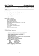
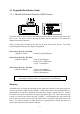
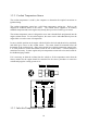
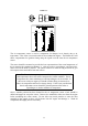
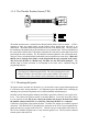
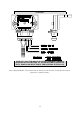
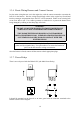
Table Of Contents
- Introduction
- SECTION 1 Getting Started
- CHAPTER 1 HALTECH IG5 INSTALLATION
- 1.1 Overview
- 1.2 Installation Summary
- 1.3 Expanded Installation Guide
- 1.3.1. Manifold Absolute Pressure (MAP) Sensor
- 1.3.2. Coolant Temperature Sensor
- 1.3.3. Inlet Air Temperature Sensor
- 1.3.4. The Throttle Position Sensor (TPS)
- 1.3.5. Mounting the Igniter
- 1.3.6. Route Wiring Harness and Connect Sensors
- 1.3.7. Power Relays
- 1.3.8. Electronic Control Unit (ECU)
- 1.3.9. Flying Leads
- 1.3.10. Install and connect any Optional Outputs
- 1.3.11 Connect the Trigger Sensor
- 1.3.12 Connect the ECU
- CHAPTER 2 GETTING ONLINE
- CHAPTER 3 ENGINE IDENTIFICATION
- CHAPTER 4 USING HALTECH SOFTWARE
- CHAPTER 5 STARTING THE ENGINE
- CHAPTER 1 HALTECH IG5 INSTALLATION
- SECTION 2 Other Adjustable Features
- SECTION 3 Software Features
- SECTION 4 IG5 Optional Outputs
- CHAPTER 12 SOFTWARE ACCESS
- CHAPTER 13 AUXILIARY OUTPUTS
- 13.1 Description
- 13.2 Turbo Waste Gate Control (TWG)
- 13.3 Dual Intake Valve Control (DIV)
- 13.4 Torque Converter Lockup (TCC)
- 13.5 Electric Thermatic Fan Control (TF)
- 13.6 Electric Intercooler Fan Control (IF)
- 13.7 Shift Light Illumination (SL)
- 13.8 Anti-Stall Solenoid Control (AS)
- 13.9 Turbo Timer (TT)
- 13.10 NOS Switch
- SECTION 5 Appendices

8
SECTION 1 Getting Started
CHAPTER 1 HALTECH IG5 INSTALLATION
1.1 Overview
The Haltech IG5 system comprises the following components
Haltech Electronic Control Unit (ECU)
Main Wiring Harness
Haltech IG5 system Instruction Manual
Programming Cable
Programming Disk
Relay
Optional Items (at extra cost)
Coolant Temperature Sensor
Inlet Air Temperature Sensor
Throttle Position Sensor (TPS)
Manifold Absolute Pressure (MAP) Sensor, (1,2 or 3 Bar)
Ignition Module
Ignition Timing Trim Control
Reluctor Adaptor - for magnetic triggers
Ignition Coils
Haltech Dual Hall-Effect sensor
1.2 Installation Summary
1. Mount Manifold Absolute Pressure Sensor. (If applicable)
2. Mount Coolant Temperature Sensor. (If applicable)
3. Mount Inlet Air Temperature Sensor. (If applicable)
4. Mount Throttle Position Sensor. (If applicable)
5. Mount Ignition Module
7. Route Main Wiring Harness and connect sensors and ignition module.
8. Mount and connect Power Relay.
9. Mount ECU inside passenger compartment.
10. Locate and connect flying wires:-
RED + 12 volts battery
GREY Ignition on 12 volts
BLACK Chassis ground
11. Install and connect any Optional Outputs
12. Connect Trigger signal
13. Connect ECU and test.