V 2.
Contents at a Glance F9 Page Introduction ................................................................ 7 Section 1 ...............Getting Started Chapter 1..................... Installation................................................ 15 Chapter 2..................... Getting Online.......................................... 26 Chapter 3..................... Engine Identification................................ 31 Chapter 4..................... Adjusting Haltech Maps ..........................
F9 Table of Contents Introduction Introduction ............................................................................................... 7 Installation Overview....................................................................... 7 Before You Begin ............................................................................ 8 Tool/Supply Requirements .............................................................. 9 How It Works..........................................................................
Chapter 3 - Engine Identification ............................................................ 31 3.1 Checking the Identification .................................................. 31 Chapter 4 - Adjusting Haltech Maps....................................................... 34 4.1 What are maps? .................................................................... 34 4.2 What is mapping the Engine?............................................... 34 4.3 Using the Software .......................................
Section Three .......Software Features Chapter 9 - File Storage and Retrieval.................................................... 56 9.1 Saving Maps and Identification............................................ 56 9.1.1 The Save Command.................................................. 56 9.1.2 Giving Your Map A Filename.................................. 56 9.2 Loading Maps and Identification ......................................... 57 9.3 File Management...................................................
C.4 Fuel Pump Capacity ............................................................. 73 C.5 Fuel Rails and Pressure Regulators...................................... 74 Appendix D - Wiring Diagrams ..............................................................
F9A Table of Contents Introduction ............................................................................................. 79 Chapter 1 - Wiring Notes ........................................................................ 80 Chapter 2 - Using the Software Features ................................................ 81 2.1 Enabling Options.................................................................. 81 Chapter 3 - Idle Speed Control................................................................
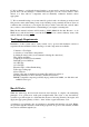
Introduction Congratulations on your decision to install a Haltech Engine Management System to your vehicle. Haltech EFI systems have been successfully installed on thousands of vehicles, from power off-shore boats to twin-turbo Ferraris, from pylon racing aircraft to jet skis and snowmobiles.
tuning your Haltech system far easier than tuning a carburettor or mechanical injection system, and with much better results. Before You Begin... 1) IT IS BEST TO READ THIS ENTIRE MANUAL BEFORE STARTING. At the very least, you should read Section One of the manual, and any of the Appendices that are relevant to your installation. The greater your knowledge of the operation of the Haltech system, the easier you will find it to understand what you are doing, and why.
6) In hot climates, or with turbocharged engines, you may need to employ heat shielding to prevent heat soak and damage to electrical and fuel parts. Use the coolest surfaces of the chassis as a heat sink for components and use thermally conductive brackets where appropriate. 7) We recommend having your system tuned by professionals. An exhaust gas analyser and fuel pressure meter make tuning vastly easier and help avoid potentially disastrous lean out conditions that could destroy your engine.
Electronic fuel injection revolves around the use of solenoid actuated injectors. These devices employ a coil attached to a valve. When the coil is energised, the valve opens and fuel is allowed to flow. As long as the pressure between the fuel and the air in front of the injector nozzle is held constant, the rate of fuel flow will remain the same. By accurately controlling the length of time the injector remains open, precise quantities of fuel can be metered to the engine.
The Advanced Mode Features of the F9A This is an upgraded version of the F9 with expanded capabilities in controlling and using various engine accessories. The F9A can perform such functions as Turbo Waste Gate control, Closed Loop Lambda control, etc. If you have purchased an F9A, these extra options would already be available. Refer to the F9A Section of this manual for instructions in using the extra functions.
Haltech F9 Specifications Engine Suitability • • • • • • up to 16,000 rpm 1, 2, 3, 4, 5, 6, 8, 10, 12 cylinders (1-2 rotors)* 2 or 4 stroke normally aspirated or supercharged up to 200 kPa (30 psi) load sensing by throttle position or manifold pressure multipoint, batch-fire, staged injection Power Requirements • Power Source 8.6 to 16 Volts DC • Consumption Haltech ECU: 270 mA at 12 Volts Injector Load: Dependent on injector type approx. proportional to injector duty cycle (typically 0.
• Throttle Position Sensor 10 kΩ rotary potentiometer driven from throttle shaft • Engine Speed Pickup Compatible with most trigger systems: - 5 or 12 volt square wave; - pull-to-ground (open collector) Tach adaptor available for magnetic (or ‘reluctor’) triggers ECU Outputs • Injector Driver 4 x 4/1Amp peak-and-hold current limiting drivers: - up to four low-impedance injectors* - up to eight high-impedance injectors* (Expandable using optional Driver Box.
Coolant Temperature Enrichment - 32 points Air Temperature Adjustment - 32 points Battery Voltage Correction - 32 points Closed Throttle (selectable) - 16 points Full Throttle (selectable) - 32 points • Programmable Rev-Limit • Fuel Cut on Deceleration • Accelerator Pump Increase and sustain parameters Coolant enrichment factor Three speed ranges • Idle Speed Control Target Idle Speed Cold Idle-up Rpm Post-start Rpm setting • Closed Loop Control with both cruise and idle settings • Programmable Output Optio
SECTION ONE Getting Started CHAPTER Haltech F9 Installation 1.
1.2 Installation Summary 1. 2. 3. 4. 5. 6. 7. 8. 9. Mount Manifold Absolute Pressure Sensor. Mount Coolant Temperature Sensor. Mount Inlet Air Temperature Sensor. Mount Throttle Position Sensor. Route Main Wiring Harness and connect sensors. Mount and connect Power Relays. Mount Fuse Block. Mount ECU inside passenger compartment. Locate and connect flying wires:RED + 12 volts battery GREY Ignition on 12 volts BLACK Chassis ground ORANGE (2 wires) Fuel Pump Circuit BROWN Trigger Input 10.
2 Bar Sensor (Part No. 886 3189) (-100kPa to 100kPa) Turbo or Supercharged Engines up to 100kPa boost (15 psi, 1 atmosphere) 3 Bar Sensor (Part No. 749 3169) (-100kPa to 200kPa) Turbo or Supercharged Engines up to 200kPa boost (30 Psi, 2 atmospheres) Note: Make sure you have the correct MAP sensor for your engine. The first three digits of the part number is stamped on the sensor housing.
The coolant temperature sensor is designed to screw into a threaded hole and protrude into the engine coolant stream. For air cooled engines, the sensor can be embedded directly into the engine block or used to sense oil temperature. Locate a suitable position on the engine which will allow the hole and thread to be machined, and which gives access to the coolant stream. The sensor should be mounted after the engine and before the thermostat in the coolant circuit.
1.3.3. Inlet Air Temperature Sensor 14mm x 1.5 The air temperature sensor is used to compensate for changes in air density due to air temperature. Cold air is denser than warm air and therefore requires a greater volume of fuel to maintain the same air/fuel ratio. This effect is most noticeable in forced induction engines. The Haltech F9 will automatically compensate using the signal received from the air temperature sensor.
1.3.4. The Throttle Position Sensor (TPS) The throttle position sensor is mounted to the throttle butterfly shaft to measure its rotation. A TPS is common on many late model engines and the Haltech sensor should attach with little or no modification. The throttle shaft must protrude from the side of the throttle body. This may require the machining of the throttle body or the manufacture of a new throttle shaft. The inner mechanism of the sensor rotates with the shaft.
1.3.6. Power Relays There are two relays used with the Haltech F9, the Main Power Relay (with a grey wire) and the Fuel Pump Relay (two orange wires). These relays are identical parts so it is not important which relay goes in what connector. These relays should be mounted on the firewall or an inner guard. Do not mount the relays such that they could catch and collect splashed water. Residual water inside the relay housing will cause them to fail. Mount them with the tab upwards as shown in the diagram.
The fuse block should be positioned so that it can be easily accessed in case of fuse failure. Do not mount the fuse block where it could be exposed to water. Mount via the two screws holes in the block. Ensure that vibration will not cause the screws to vibrate loose. Connect the Fuse Block assembly to the Main Harness. 1.3.8. Electronic Control Unit (ECU) The Haltech F9 is not designed to be waterproof. It is desirable that the ECU be given as much protection from the environment as possible.
1.3.9. Flying Leads Locate and connect the following flying leads. Black - (Ground) Locate a good chassis ground point and connect the black wire. The best spot is direct to the battery negative terminal. Red - (Supply 12V) Locate a source of continuous 12 volts and connect the red wire. Connecting direct to the positive battery terminal is suggested. Grey - (Switched 12V) The grey wire is used to control the operation of the Haltech F9 power relay.
1.3.10. Configure Trigger DIP - Switches The input trigger is used by the F9 to determine engine speed and when to fire the injectors. The standard connection for this wire is to the negative terminal of the ignition coil. If the engine does not use standard points or a electronic ignition system then it may be necessary to reconfigure the input circuit. The trigger configuration DIP switches can be found by removing the back cover from the F9 ECU.
Switch Category A Category B Category C Category D 1 OFF OFF OFF ON 2 ON OFF OFF OFF 3 ON ON OFF OFF 4 ON OFF ON ON 5 OFF ON ON ON 1.3.11 Route Optional Auxiliary Loom The auxiliary loom may be routed in a similar manner to that of the main loom. Refer to the F9A Supplementary Manual for installation details. 1.3.12 Connect the ECU The ECU can now be connected and tested. Be sure to engage the clip on the main connector.
CHAPTER Getting Online 2 Now that your Haltech F9 is installed with all the sensors in place the system can be connected to the programming computer. This will allow the readings from all the sensors to be displayed on the screen and checked for correct operation. To connect the PC to the Haltech F9 ECU you will need the programming cable and programming disk supplied. 2.1 Connecting the Haltech F9 to a Computer The programming cable supplied with the Haltech F9 is a standard serial link extension cable.
supplied. Installing the software on the Hard Disk will speed up the programme and avoid having to fiddle around with floppy disks. The installation programme need only be run once. If you do not have a Hard Disk, go to the section titled Running the Software from the Floppy Drive. To install the software follow these steps. Boot up Computer Turn your PCs power on and boot up MS-DOS as instructed by the computers Users Manual.
The F9 Programme is now ready to run. 2.2.3 Running the Software from the Hard Disk. Boot your computer up as described earlier. If your computer is already on, make sure the C drive is currently selected. To change to the HALTECH directory type : F' ?KDOWHFKy or, if you used a different destination directory, type that path. To start the programme type : I y The F9 programme will now run. The next section is on running the software from a floppy drive.
H Dy to run the programming software (not the installation software), you need to instead type : H D Dy The /A tells the programme you have an Azerty keyboard. The programme will adjust accordingly. 2.2.6 Acknowledging the Risks Once the program begins running a title page should appear briefly and then a warning screen will be displayed. Read the warning and only proceed if you are prepared to accept the risks involved in tuning your own engine.
NOTE: If power is removed or the communication cable is disconnected or interfered with, the following message will be displayed on the computer screen. RECONNECT HALTECH If this message appears check all connections and ensure that the communications cable is not being interfered with. Also be sure that the Haltech F9 unit is receiving power. (i.e.. ignition switch is turned "on".) 2.5 The Main Menu When you select Online or Offline mode the Haltech MAIN MENU bar appears.
CHAPTER Engine Identification 3 3.1 Checking the Identification The Identification page tells the F9 essential information about the engine characteristics. Without this information being correct the engine cannot run properly. The Identification is made up of several fields. Each field can have a number of settings, and you can change most of the fields. Use the Up and Down arrow keys (o and p) to move between fields. The fields are either Selection type, or Text type.
RPM Mode: The F9 fuel and ignition maps may be arranged either in 500 rpm increments to 10,500 rpm, or in 1000 rpm increments to 16,000 rpm. Select the high - or low - rpm mode here. Changing settings alters the way the ECU reads the Maps, and will change the tuning of the engine dramatically. Do not change this setting once tuned unless necessary. Road Speed Value: This value calibrates the Road Speed reading.
Aux. In/Out Function: The Auxiliary Input/Output on the F9 can be configured for one of several functions. Most of these functions relate to the configuration of the system. The available functions are: Disabled No effect on ECU operation. Staging Signal Output - Logic output that indicates Staging conditions. If Staging is selected, and the Staged injector are firing, this signal will be high (5 volts), otherwise it will be low (~ 0 volts).
Chapter Adjusting Haltech Maps 4 The tutorials presented in this chapter are examples of how you might use the available functions to make typical modifications to the maps. These tutorials are aimed at explaining both why and how some typical changes might be made. They assume that you have the software running Online on your PC, with the ECU powered and connected via the supplied programming cable. 4.
4.3 Using the Software In order to make the software easy to use, the programme presents you with a menus bar at the top of the display. The menu bar is accessed through simple combinations of key strokes. Once the appropriate menu has been accessed a sub-menu appears giving choices on available page heading. To increase efficiency there is also a number of hot-keys that allow you movement between pages without accessing the menu bar. 4.4 Accessing the fuel maps Pressing sP will take you to the Maps Menu.
injectors, adding to their fuel flow. The point at which the F9 switches in the secondary injectors is set via the Staging Bar Number field. Staging permits high fuelflow capability, but maintains accuracy and controllability at light load and idle. See Appendix D [D.3] for more details on staging. Staging Bar Number: This field sets the point at which the staged injectors are enabled. See Appendix D [D.3] for more details on staging.
To view the map at the 3000 rpm range, press d. When in the Fuel Maps sub-menu your display should look like this: HALTECH F9 Fuel Map Values from this bar chart would be used whenever the engine speed falls in the range between 2750 and 3250 rpm (or, if in high-rpm mode, between 2500 and 3500 rpm). In the top left is the range number and the speed range to which it corresponds. Opposite, in large numerals, is the current engine rpm.
Now try using the key. The outlined bar should jump up 0.096 mS. As the bar gets taller, the fuel delivery is increased and the engine is enriched at that speed and load. Now press the key and the highlighted bar should move down 0.096 mS. Note that the fuel delivery for the outlined bar is shown in the bottom corner of the display. Note also that the injection time does not necessarily match the bar height as the injection time is the actual injection time after various corrections have taken place.
allows you to programme all rpm ranges simultaneously with the same data. sU turns All Ranges on, and the words All Ranges appears under the title. When the All Ranges function is active, a bar adjusted on one graph is copied to the same bar on all the ranges. If you use this option, you can set the shape of the map at any range, and all other ranges will be identical at every bar you adjusted. This feature enables all graphs to be given an initial shape that should run the engine, albeit rather roughly.
4.6.7 Bar Increments - sL The Up and Down arrows, p o, normally change the bar height in the maps by a predetermined amount, usually the smallest possible increment. PgUp and PgDn change the bars also by a pre-determined amount. These increments (the value of the keystroke) can be changed by the user. be changed. sL will bring you to a screen where the increments themselves can Normally, the bars are altered by adding or subtracting a fixed amount.
4.7 Duty Cycles Fuel delivery is obtained by pulsing the injectors synchronised with the engine speed, allowing fuel to flow during the period that the injector is open. The time whilst open is called the injector pulsewidth. As rpm increases it is possible for pulsewidths to overlap so that the injectors are effectively switched completely on. This is referred to as 100% duty cycle. When 100% duty cycle is reached the fuel flow from the injectors has reached its maximum.
42
4.
Chapter Starting the Engine 5 There are a few things that need to be done before the engine should be started. Make sure that the ECU is powered (ignition on) and the Haltech Software is Online. Go to the Engine Data Page to check that the ECU is communicating properly, and that the sensors are reading correctly. Check again that the Main Setup, and Fuel Setup are all set correctly. In particular, check the No. Cylinders, Ign Div/By, Load Sensor and Injection Mode parameters.
If the engine misfires and blows black smoke then the mixture is rich and the bars need to be lowered. If the engine will not fire or fires but will not continue to run then the mixture could be lean and the bars need to be increased. 5.3.1 Tuning for Idle The idle mixture is very sensitive to correct bar height. Idle injection times are usually around 1.5 to 2.5 mS. If the injection time at idle is much lower than this, it may become difficult to set accurate idle and cruise air:fuel ratios.
5.3.4 On the Dyno Whether the vehicle is on a chassis dyno, or the engine on an engine dyno, the principles of programming the Haltech F9 are the same. Take the engine rpm up to 1000 and apply partial load and adjust the 1000 rpm range. Return the engine to idle and on the 1000 rpm range adjust the bars to draw a straight line from the idle point through the part load setting tested. Continue, adding more load, up to the full load settings. This should be a fairly good approximation to the required curve.
HALTECH F9 Fuel Map Left: a typical fuel curve for a normally aspirated engine at idle speeds. HALTECH F9 Fuel Map Right: a typical fuel curve for a TPS mapped engine.
SECTION TWO Other Adjustable Features Chapter Throttle Effects 6 6.1 Throttle Response Where the procedures described in the previous chapter tune for constant load running, the functions outlined in this section will improve the throttle response of your engine. The manifold pressure sensor used with the F9 is very fast. It can respond much faster than is required to track any sudden changes in load on your engine.
The heights of the increase bars and the sustain bars are adjusted using the same keys that are used for adjusting the fuel curve bars. The left and right arrow keys allow you to move from one bar to the next. The throttle pump values should be set up after the fuel and maps are correctly tuned for steady load running. Attempting to smooth out engine transients before the fuel maps have been optimised for steady state running may become confusing.
6.3 Full Throttle Map The manifold and throttle body design can also cause problems tuning at full throttle on normally aspirated engines. In some cases, the manifold pressure can reach close to atmospheric pressure before full throttle is reached. This means that bars close to the full load bar on the Fuel Maps can interfere with the full load bar due to the interpolation between the two bars.
Chapter Cold Starting and Running 7 The Haltech F9 has features to modify fuel delivery to aid in starting and running a cold engine. The Cold Start Prime map gives a cold engine an initial burst of fuel just as the engine begins cranking. The Coolant Correction Map modifies the normal fuel injection until the engine reaches normal operating temperatures. 7.1 Cold Cranking At cold crank the air speed at the inlet manifold is very low.
7.2 Fuel Correction Versus Coolant Temperature Once started, an engine requires more fuel when it is cold than when it is hot. This is a result of low manifold and in-cylinder temperatures where fuel sticks to the walls and doesn't burn properly. The Haltech system corrects for this by using the Fuel Coolant Map to define the relation between engine temperature and extra fuel required.
Chapter Correction Factors 8 The Haltech F9 has two further correction maps to compensate the fuel for changes in inlet air temperature and battery voltage, and also two correction Maps to adjust ignition timing for coolant and inlet air temperatures. MOST USERS SHOULD NEVER ADJUST THESE MAPS. These maps are factory set to provide excellent correction for almost all engines.
8.3 Barometric Correction Fluctuations in barometric pressure varies the density of the intake air of the engine. At lower barometric pressure, the engine can not breath in as much air, and therefore the amount of fuel delivered to the engine must be reduced. In mapping in Throttle Position Mode, the Map sensor provides a reading used for Barometric Correction. When in Manifold Pressure Mode, there are two forms of Barometric Correction performed by the F9 and a third which is only available on the F9A.
correction. For example, if an engine is tuned at sea level but is intended to be used mainly at a higher altitude, then the reset should be performed once it reaches its new regular location. After that, the automatic reading done at start up will be sufficient. The third, F9A only, form of Barometric Correction is performed using a separate Barometric pressure sensor.
SECTION THREE Software Features Chapter File Storage and Retrieval 9 Once your Haltech F9 system is configured you should store the entire set of maps and the Identification to disk. In fact, it is wise to save maps regularly during tuning so that you can return to a known map while you are experimenting in different areas. You can use the file storage and retrieval to enhance the flexibility of your race engine by storing the optimum maps for each race track.
After you have chosen a name for the maps, you must enter the name in the space provided. The system will pause and ask if it is OK to continue with the save. If everything looks correct, continue by pressing <. If you entered the name incorrectly, abort the Save function by pressing 1, or 5 to re-enter a name. 9.2 Loading Maps and Identification While the ECU system is Online, you can load previously saved map information from computer disk into your Haltech ECU.
9.3.2 Changing Directories If files can be likened to books in the library, then directories are analogous to names on the shelves. Directories can be used to group related files together. To change directories when loading, saving or erasing maps, press sF. The Files List will now display all directories in square brackets. Select the directory you want using the Up and Down arrows, and pressing Return.
Chapter Printing Maps 10 10.1 The Print Function You can print the maps and identification information to printers that accept IBM emulation mode, such as IBM compatible dot matrix printers (consult your printer manual). The Print function should work with other dot matrix printers, but some special characters such as °, ±, etc. may not print correctly. Select the print function by pressing S from the Options submenu The system will present you with options on which data you wish to print.
Chapter DataLog 11 11.1 The Datalog Option This option records the Engine Data information at approximately five times per second while the engine is running. This datalog is useful for tracking the system's behaviour through changing rpm. It also facilitates trouble-shooting, as all the ECU's working parameters are recorded faster than they can be read on the Engine Data Page. The Datalog Menu is accessed through the Options Menu. (Press sR).
11.1.3 Viewing the Datalog To view the datalog you have just taken, press 9 from the Datalog sub-menu. The Engine Data information will appear as rows across the screen, with a time index at the end of the row. At the bottom of the screen is a list of the command keys.
Before loading a Datalog from disk, you should load the Maps that were saved with it so that the programming software knows the setup of the ECU and can calibrate the data properly. Do not load a Datalog when Online to the ECU, or else the Maps you load will overwrite the Maps in the ECU. If you want to view a saved Datalog, switch to offline mode, load the appropriate map, and then load the Datalog. 11.1.
Chapter Customising the Software 12 12.1 The Setup Page The Setup window allows you to change the way the software works for you. If you alter any of the parameters on this page, the programming software will remember the changes you have made and they become the default settings. The next time you run the Haltech programme, the settings will be as you left them. The Setup Window is accessed from the Setup menu by pressing sV. Or by pressing tS.
SECTION FOUR Appendices Appendix Troubleshooting A This Appendix is devoted to trouble shooting problems that may occur during setting up the F9 on your engine. To use this Appendix, firstly identify the closest symptom or symptoms from the list below, and then follow the check-list for possible solutions. A.1 Overview Control Programme Problems • The Haltech Programming Software will not load up • The Haltech Programming Software will not operate in Online mode.
Fuel Economy problems • Poor fuel economy - city cycle • Poor fuel economy - Highway cycle A.2 Control Programme Problems Haltech Programming Software will not start up The Haltech programming software should run on any computer that meets the requirements in Chapter 3. If, after following the instructions in Chapter 3, the programme will not run, the most likely cause will be insufficient memory. If this is the case, you must make more free memory available before running the software.
Engine Data Page Displays Unusual Readings If the air temperature sensor, or coolant temperature sensor is showing a FAULT condition then the sensors are either not operating correctly or are disconnected. Using the wiring diagram of the Haltech F9 Loom check that the sensor wires are not damaged. If the wiring is OK then contact your Haltech dealer regarding replacement of faulty sensor.
If the engine will not idle when cold but will when the engine is warm then the coolant correction map needs to be adjusted. If you are not using an idle air control motor then adjust the idle using the idle adjust screw on the throttle body. Check for any air leaks in the manifold. If the engine surges or hunts at idle then the mixtures and timing are wrong. Readjust the fuel maps near idle conditions. In some circumstances it may be necessary to use the Zero Throttle Map. Consult Chapter 6 [6.
A.8 Cold Running Problems If the engine idles poorly when cold then the coolant map may need adjusting. If the engine is hunting slightly when cold, then the coolant correction map is just too lean, and so needs a small amount of enrichment. Slight advance with the coolant temp. can help. If the engine is difficult to drive when cold, particularly with gear changes, try increasing the coolant correction factor for the throttle pump.
Appendix Injector Impedance B Electrically, there are two different types of electronic fuel injectors. One type of injector, characterised by a high coil impedance (> 12Ω) is known as saturation injectors. The other sort of injector, typically with coils of less than 6 ohms impedance, is known as peak-andhold injectors. The names are derived from the current waveform that accompanies the injector when it is switched on. Saturation, or high impedance, injectors, require a simple switch to operate.
your Haltech dealer for advice. NB: Under no circumstances should you mix saturation and peak-and-hold injectors on the one driver. This will lead to erratic injector operation.
Appendix Fuel Systems & Staging C The best EFI installation will yield poor results if the fuel system does not meet the demands of the engine. Insufficient fuel flow can lead to engine lean out and detonation which could cause serious damage. For the safety of your engine, we urge you to check your fuel system's capacity and ensure that there will be sufficient supply at all times.
exceed 85% duty cycle injection on time, and that at high rpm, injector dead time can consume a significant amount of available injection time. If you find that your injector flow is insufficient, you can change to larger injectors, add extra injectors, or increase fuel pressure. Raising fuel pressure to increase injector flow rate is not recommended if the desired flow is more than 20% than the system currently achieves. Fuel flow is not in direct proportion to fuel pressure.
HALTECH F9 Fuel Map Staging is enabled on the Fuel Setup by selecting the "Staged" Injection Mode. The Staging Bar is also defined on the Setup (see Chapter 3). Once staging is enabled, the bars on the Fuel Maps will change appearance. The bars that indicate both sets of injectors firing are a different colour to those corresponding to primary injectors firing alone. When staging injectors, drivers 1 and 2 are primary and drivers 3 and 4 are secondary.
If you cannot achieve the required fuel flow from one pump, you can employ two pumps in parallel. If you choose to use a low pressure pump to augment the fuel flow of a high pressure pump, place a check valve after the low pressure pump. C.5 Fuel Rails and Pressure Regulators A long fuel rail with narrow internal diameter will suffer from pulsation in the fuel rail. The internal rail diameter should be around 12mm (½"). Even so, oscillations may occur, particularly if the injectors are large.
Appendix WiringDiagrams 75
J 1: E C U P R IM A R Y C O NN E CT O R A MP 17 2 0 47 - 2 P IN : 1 7 0 32 1 -1 GN D TR I G GE R TX RX PU M P R E LA Y AU X IN 1 T RI M MA P + 5 VD C CO O L AN T I NJ 2 I NJ 1 I NJ 3 I NJ 4 GN D + 1 3. 8 VD C EC U GN D GN D A IR T EM P T H RO T TL E PO S 1 2 3 4 5 6 7 8 9 10 11 12 13 14 15 16 17 18 19 20 B LK B RN R ED B LU B LK / YE L B LU B LK / WH T Y EL O RG V IO B LU / RE D L .
HALTECH F9A SUPPLEMENTARY INSTRUCTION SECTION 77
Introduction This section provides information only on the operation and use of the options that are available with the F9A system. The previous section of the manual relates to the Haltech™ F9, which explains in detail the fitting and programming of the system. The F9A executes the fuel delivery in the same manner as the standard F9. However, the F9A incorporates a number of auxiliary outputs which can control various devices.
Chapter Wiring Notes 1 You will have received mating connectors, pins and seals for two of the connectors on the F9A secondary harness. These are for the Auxiliary I/O connector and the Road Speed connector. Refer to the diagrams below, or the loom wiring diagram at the back of this manual for pin-out information. The main connector on the secondary harness plugs directly into the ECU. The two-way power connector on the primary harness feeds +12V and ground to the secondary harness.
Chapter Using the Software Features 2 The Output Options Page The Output Options Page is where all F9A options are enabled/disabled and programmed. This page may be accessed in either Online or Offline mode. Remember that any changes you make in Offline mode will not affect the ECU. Pressing sR will take you to the Options Menu. Press 2 to go to the Output Options Page. Alternatively use the tR hot key combination Here, the five F9A options are shown in five windows.
Chapter Idle Speed Control 3 A bipolar stepper motor may be used to control the ingress of additional air to the engine while the throttle is closed. This is useful for maintaining steady idle under changing load conditions, e.g. as air conditioner compressors or headlights are switched on and off. The stepper motor may also be programmed to increase the idle rev-rate just after starting, or while the engine is still cold.
The idle speed motor is only adjusted when the ECU determines that the engine is in an idle condition; that is, throttle closed (0%), and engine speed and manifold pressure within limits (see below). There are ten parameters to be adjusted in the idle speed control. Enable/Disable: The Idle Speed Control can be switch on or off. Target Idle Speed: This is the engine speed that the ECU attempts to maintain at idle. Cold Idle-Up RPM: This speed is added to the Target Speed when the engine temp is cold.
Chapter Closed Loop Control 4 By fitting an oxygen sensor to the exhaust system of an engine, the F9A is able to perform a feedback correction to maintain a consistent air-fuel ratio around stoichiometric mix; i.e.. when exactly the correct amount of fuel is provided to consume all the oxygen of the air drawn into the engine, without any unburnt fuel remaining after combustion.
Lower RPM Limit: The engine must be running above this speed for the closed loop function to operate. Normally this would be set a few hundred rpm above or below idle, depending on whether you wish closed loop control to occur at idle speeds. Upper Throttle Limit: It is generally undesirable to run an engine at stoichiometric air-fuel ratio when under load. This parameter is used to determine when the driver is demanding sufficient engine output to disengage the closed loop function.
control, but rather as an aid during tuning. To use a 5 volt sensor, a jumper shunt needs to be installed on the F9A circuit board. This shunt may be later removed when the UEGO probe is replaced by the standard 1 Volt sensor once tuning is complete. Please contact your HaltechTM representative for details on using this feature. Using Different Oxygen Sensors Almost any oxygen sensor can be used with the F9A. The sensor available from HaltechTM is an NGK heated four wire oxygen sensor.
Chapter Auxiliary Outputs 5 The F9A possesses three output channels, each of which may be programmed to perform a certain function. Each output channel is a pull-to-ground style signal suitable for switching solenoids, relays or low-power dashboard lamps. Each channel employs a 4.0A peak / 1A hold current driver. This is suitable for driving most relays, solenoids, and other low power devices.
5.1 Turbo Waste Gate Control (TWG) The wastegate of a turbo is operated when the manifold pressure is sufficiently high to force the diaphragm within the wastegate unit. With electronic boost control, the object is to use a pulsating solenoid to bleed off the manifold pressure signal seen by the waste gate unit so that it can see only a fraction of the manifold pressure. The solenoid operates at constant frequency and the duty cycle is altered to control the drop in pressure signal through the device.
Once the solenoid installation is complete run the F9 software in Online mode. Select the Turbo Wastegate Control Function on the appropriate output channel, and set the following parameters. Period: This sets the period of oscillation of the solenoid. Most solenoids will operate at around 30Hz, which corresponds to a period of about 30mS. Enter the desired oscillation period in milliseconds here.
Boost Map. The Maximum Boost Map should always contain values greater than or equal to the corresponding values in the Standard Boost Map. The use of two independent boost maps allows an engine to be set up for maximum boost conditions, but driven safely at lower boost pressures without the need of re-loading maps.
switch input. This signal indicates that the transmission is hot, and engaged in top gear. When this is the case, the lockup solenoid is activated regardless of road speed whenever the throttle is more than 4% opened.
5.4 Electric Thermatic Fan Control (TF) This function can be used to switch on a thermofan when the engine temperature exceeds a certain value. The fan will stay on until the engine temperature drops below a second value. NB: The electric fan cannot be driven directly by the ECU. A relay must be used to switch the high currents drawn by the fan.
5.5 Electric Intercooler Fan Control (IF) This function can be used to switch on an electric fan on the intercooler when the inlet air temperature exceeds a certain value. The fan will stay on until the temperature drops below a second value. NB: The electric fan cannot be driven directly by the ECU. A relay must be used to switch the high currents drawn by the fan.
5.6 Shift Light Illumination (SL) The F9A can be used to activate a shift light or a piezo buzzer when engine speed exceeds the programmed activation speed. To use the shift light function, you will need the following: - the F9A secondary harness incorporating the Auxiliary I/O connector; - a dashboard lamp or buzzer; - F9 programming software and cable. The lamp or buzzer should be wired to +12V on one side, and the other to the ECU. The lamp used must not draw more than 0.5 amp of current (i.e.
Engine Speed: The extra fuel pump will turn on when the engine speed exceeds this parameter. If you wish to switch the pump only by load, set this parameter high. Run Time: The auxiliary fuel pump will switch on if the engine exceeds the engine speed and/or the load bar set above. It will then stay on, even after speed and load have dropped below their respective limits, for a period of time specified by Run Time. A minimum Run Time of 5 seconds is permitted.
5.8 Anti-Stall Solenoid Control (AS) A solenoid air valve in the manifold may be used to allow extra air into the engine during cranking or extremely low rpm. This can aid in starting the engine, or in preventing it from stalling if engine revs drop too low. To use this function, you will need the following: - the F9A secondary harness incorporating the Auxiliary I/O connector; - a suitable solenoid air valve mounted to the manifold; - F9A programming software and cable.
5.10 Turbo Timer (TT) When an engine is switched off, oil is no longer being pumped to the turbocharger. This is common cause of turbo wear if the turbocharger is no allowed to slow down before an engine is switched off, cause it to spin for an extended time unlubricated. This function controls the ignition power via relays to keep the engine running for a period of time after the ignition switch has been turned off.
Appendix Wiring Diagrams A J2: ECU SECO NDARY CONNECTOR A MP 172 02 1-2 P IN: 17 03 21-1 IDL4 IDL3 IDL2 IDL1 SP AR E A/D GND O2 S ENSOR AU X IN2 +5VDC R OA D SPEED GND A UX OUT3 A UX OUT1 A UX OUT2 1 2 3 4 5 6 7 8 9 10 11 12 13 14 15 16 B RN/ WHT Y EL/ RED G RN/ YEL BRN WHT 18 18 18 18 20 AWG AWG AWG AWG AWG BLK GRY GRN ORG YEL 16 20 20 18 20 AWG AWG AWG AWG AWG 16 16 16 16 AWG AWG AWG AWG BLK BLK/GRN L.
LIMITED WARRANTY Invent Engineering Pty Ltd trading as Haltech warrants the HaltechTM Programmable Fuel Injection System to be free from defects in material or workmanship for a period of ninety days from the date of purchase. Proof of purchase, in the form of a bill of sale or receipted invoice, which indicates that the product is within the warranty period must be presented to obtain warranty service.