
Manual


93
Using the sensor on the crank
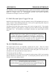
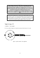
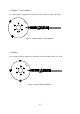
After a suitable mounting location for the sensor has been found the engine should be
positioned at approximately 75° BTDC on cylinder no.1 compression. The magnet should
now be placed in the alumin ium disk with the south pole facing towards the sensor, making
sure the magnet is in line with the sensor when the engine is in this position. This is now the
reference point for all the other magnets. The number of cylinders will determine the number
of magnets required and the angle of installation. The remainder of the magnets to be fitted
will all have a north p ole facin g the sensor.
The adjustment of the air gap will be determined by the strength of the magnets used. This
should be tested once the wheel assembly has been installed. Checking the Engine Data page
for steady RPM is usually a good indication that the air-gap is accep table.
Identifying the magnets poles
If you need to identify the magnet poles this can be done easily with the use of a multimeter
and +12V power supply. Power the sensor with 12 volts (PIN B) and ground (PIN A), the
secondary trigger channel (PIN D) can be used to identify a south pole. When a south pole is
placed in front of the sensor face, the voltage measured between the secondary channel (PIN
D) and ground (PIN A) should be zero. When a north pole or no magnet is present the
measured voltage will be +12V.
Fitting the magnets
We insist that only Haltech rare earth magnets (part number REM 1) be used for the p urp ose
of triggering the sensor. Rare earth magnets purchased from your local electronics store may
be less expensive but they are not good enough! Haltech rare earth magnets are strong, stable
at reasonably high temp eratures and have a lon g service life. There are some rare earth
magnets that are stronger magnetically, but these break down under excessive temperature, or
are too brittle for the engine bay environment and do not have a long service life. Ordinary
magnets i.e. not rare earth types, may not have the strength required for satisfactory triggering
at high sp eeds.
Haltech (part number REM 1) rare earth magnets are normally 5mmφ x 2mm deep, although
other sizes are available upon request.
The magnets should be fitted in non-ferrous surrounds such as aluminium, stainless steel or
titanium. The trigger wheel is normally made of the chosen material but various users have
reported good results when the magnets are set in a suitable non-ferrous surround and the
surround is set into a ferrous material.
The magnets should be set flush with or slightly back from the surface of the trigger wheel or
surround. If set too far back the magnetic signal may be too weak. The magnets should be set
in place with a strong and durable fixing comp ound such as high strength epoxy, Loctite stud
locking compound eg 603, or JBweld. Some users rely only on the fixing compound but to
ensure that the magnets remain in p lace but many p refer that they be retained by mechanical
means such as peening, and this gives an added safety factor.