
Manual


92
APPENDIX D TRIGGER INTERFACE
The flexibility of the F10 trigger input circuitry comes from the ability to switch certain
components in and out of the circuit allowing the ECU to interpret a range of different inputs.
(Refer 3.1.3 Trigger Set-up, 31). This appendix describes some common application
information for the trigger system of the F10 ECU.
D.1 Hall Effect and Optical Trigger Pick-ups
Hall Effect and optical trigger sy stems are common in factory EFI installations and come in a
variety of forms. These systems generally have 3 wires: power, signal and ground, the power
supply voltage required varies between sensors.
The Haltech S1/S3 Hall Effect trigger sensor can be used to trigger the F10. The principle
behind its operation is quite simple, as a magnet passes the sensor the output state changes
from high to low. The orientation of the magnets determines the output signals from the
sensor.
Note: The S1/S3 sensor is a two channel sensor (primary channel and
secondary channel) the secondary channel is used produce a synchronisation
signal. This feature is not available on the F10 ECU. The following
instructions are app licable to Haltech ECU’s with ignition control as well as
the F10. If in the future the ECU is upgraded to an ECU with ignition control,
the trigger system can be retained with a few additions
The S1/S3 Hall Effect Sensor
The original sensor, the S1, was modified to produce the S3 sensor. These two sensors
operate identically in conjun ction with the F10 and will be referr ed to from here on as the
“S3” sensor. The S1/S3 sensor can be identified by a black cable gland. The S3 sensor has a
red band near the cable gland and the S1 sensor does not.
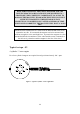
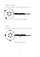
The S3 sensor op erates as follows:
As a South Pole p asses the sensor face the signal in both the p rimary (PIN C) and secondary
(PIN D) channels are switched to a low state. As a north pole p asses the sensor a low state
will only occur on the p rimary channel.
Note: magnets should always be mounted in a non ferrous material such as
aluminium, stainless steel or titanium.
Many installers have successfully mounted the rare earth magnets in non-
ferrous surrounds such as modified aluminium and stainless steel bolts, and
installed the bolts into ferrous material.