
Manual


32
Switch 3 – Pull to Ground
This switch adds a 4.7kΩ pull to ground opposing the Pull-Up 2 resistor.
Switch 4 – Filter Capacitor 1
This switch adds a 0.1uF filter capacitor to the input of the trigger circuit.
Switch 5 – Filter Capacitor 2
This switch adds a 0.001uF filter capacitor to the input of the trigger circuit after series
impedance.
Switch 6 – Resistor Bypass
This switch applies a short circuit across a 4.7kΩ series resistance on the input of the
trigger circuit.
S witch 7 – Input Impe dance
This switch allows the user to set the input p rotection impedance to either low ore
high. High is used in coil negative applications where low is used for Hall Effect or
optical digital trigger applications.
Switch 8 – Input Threshold
This switch controls the threshold voltage at which the trigger cir cuit will switch state.
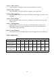
Typical Applications
Software Switches
Trigger Type 1 2 3 4 5 6 7 8
Haltech S1/S3,S2/S4 Hall
Effect Sensor
2
22
2 3
33
3 2
22
2 2
22
2 3
33
3 3
33
3
LOW 3.4V
Ignition Coil Negative
terminal
2
22
2 2
22
2 3
33
3 3
33
3 3
33
3 3
33
3
HIGH 3.4V
Driven 12V square wave
(some tacho output
signals)
2
22
2 2
22
2 3
33
3 3
33
3 3
33
3 3
33
3
HIGH 3.4V
3
33
3= On 2
22
2 = Off