
Manual


20
F10A and F10A-8 Only
1.3.11. Install and connect Optional Idle Speed Motor
If you are not using the Idle Speed Control, tie the loom connector back neatly in the engine
bay. If the engine h as a suitable Id le Sp eed M otor then you may connect it to the wiring loo m,
otherwise y ou can install a Haltech supp lied idle air control motor. For details on how to
install and plumb the Idle Speed M otor, see Chapter 14.
F10A and F10A-8 Only
1.3.12. Install and connect any Optional Outputs
If you are planning to use any of the Programmable Optional Outputs, install and connect
them now. Dep ending on what options y ou are using, the wiring will b e differ ent.
(Refer SECTION 4 F10 Inputs & Outputs, 61)
1.3.13 Connect the Trigger Sensor
The F10 requires a trigger signal on each spark event in the engine rotation ie. A 4-stroke V8
will have 4 spark events per engine rotation (or 8 spark events p er cam rotation). The trigger
signal can be one of the following:
Coil Negative:
The F10 can use the switching voltage at the negative terminal of the ignition coil as a
trigger signal in what is called a “coil negative” trigger set-up. To wire the F10 for
this trigger set-up; connect the trigger wire in the Haltech loom to the negative
terminal of the ignition coil.
Tacho Output:
Some popular ignition systems have a tacho output signal which can be used to trigger
the F10. It is necessary to use this output if the ignition system used is a Capacitive
Discharge Ignition system with a multiple spark function.
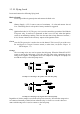
Hall Effect and Optical Triggers:
The F10 can also accep t a sign al from Hall Effect and Op tical triggers sy stems. These
trigger devices generally 3 have connections each - ground, power and the signal. The
trigger connector on the M ain Harness has six pins. These pins and their connections
are shown in the diagram below.