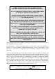
Warning This system is capable of controlling either “intelligent” igniters such as the Haltech EB023 igniter, which has in-built dwell control or “dumb” igniters which contain no such control. This allows standard igniters to be used in many cases. Most standard igniters are dumb igniters. However, it is very important to set the system up to match the type of igniter used.
Introduction ......................................................................................... 1 This Manual........................................................................................................................ 1 Installation Overview ......................................................................................................... 1 Before You Begin...............................................................................................................
4.4.2 Adjusting Bar Height In The Map....................................................................... 35 4.5 How To Quit............................................................................................................... 36 4.6 Accessing the Ignition Maps ...................................................................................... 36 4.6.1 Ignition Set-up..................................................................................................... 36 4.
11.1.1 Setting Up the Datalog Page ............................................................................. 68 11.1.2 Creating a Datalog............................................................................................. 68 11.1.3 Viewing the Datalog.......................................................................................... 69 11.1.4 Datalog File Management ................................................................................. 69 11.1.5 Printing Datalogs..............
A.1 Overview ................................................................................................................. 103 A.2 Control Program Problems...................................................................................... 104 A.3 Starting problems .................................................................................................... 105 A.4 Idling Problems ....................................................................................................... 106 A.
Under copyright law, neither this manual nor its accompanying software may be copied, translated or reduced to electronic form, except as specified herein, without prior written consent of Lockin Pty Ltd trading as Haltech. Copyright 1999 Lockin Pty Ltd A.B.N. 68 061 744 303 Trading as HALTECH 10 Bay Road Taren Point, NSW 2229 Australia Ph: (+61) (02) 9525 2400 Fax: (+61) (02) 9525 2991 Sales-au@haltech.com www.haltech.com MS_DOS is a registered trademark of Microsoft Corporation.
Introduction Congratulations on your decision to install a Haltech Engine Management System to your vehicle. Haltech EFI systems have been successfully installed on thousands of vehicles, from power off-shore boats to twin-turbo Ferraris, from pylon racing aircraft to jet skis and snowmobiles.
mount and connect the ECU itself. Haltech systems provide electronic fuelling control. The engine must already be configured with intake manifold and suitable injectors, a fuel rail with pressure regulator, and a high-pressure pump. To control ignition timing, the ECU requires a fixed trigger from a distributor, crank angle sensor, or cam angle sensor. If your vehicle lacks one or more of these components, your Haltech dealer can help you obtain them.
WARNING: AVOID OPEN SPARKS, FLAMES, OR OPERATION OF ELECTRICAL DEVICES NEAR FLAMMABLE SUBSTANCES. ALWAYS DISCONNECT THE BATTERY CABLES WHEN DOING ELECTRICAL WORK ON YOUR VEHICLE. DO NOT CHARGE THE BATTERY WITH A 24VOLT TRUCK CHARGER OR REVERSE THE POLARITY OF THE BATTERY OR ANY CHARGING UNIT DO NOT CHANGE THE BATTERY WITH THE ENGINE RUNNING AS THIS COULD EXPOSE THE ECU TO AN UNREGULATED POWER SUPPLY THAT COULD DESTROY THE ECU AND OTHER ELECTRICAL EQUIPMENT.
Tool/Supply Requirements Installation of this system can be easily carried out by professional mechanics and most experienced home mechanics if the following tools and components are available: Voltmeter or Test Light A selection of screwdrivers and spanners Soldering Iron and solder (we recommend soldering all connections) Wire Cutters and Pliers Crimping Tool and assorted terminals Drill with assorted drill bits 3/8" NPT Tap 14mm x 1.
combination of engine speed and load, we have a direct reference to the amount of air that is being drawn into the engine by means of this map. The Haltech E6H/E6M uses a digital microcomputer to measure engine speed and load, and uses them to access the base fuel map. The base fuel map is a look-up table of injector opening times stored in non-volatile memory i.e. when power is switched off, the contents of the memory are retained.
meets any of the criteria, you should use the Advanced Mode when programming the E6H/E6M. If your engine does not meet any of the criteria, program in Basic Mode. The Advanced Mode will not provide you with any extra abilities or features, but may only complicate some issues. Setting the programming mode is described in Chapter 3 Engine Identification [3.1]. Once the Advanced Mode is set when the PC is on line to the Haltech, it will not need to be switched on again, even if you exit the program.
HALTECH E6H/E6M SPECIFICATIONS Engine Suitability • • • • Up to 16,000 rpm 1, 2, 3, 4, 5, 6, 8, 10, 12 cylinders (1-2 rotors)* 2 or 4 stroke Normally aspirated or supercharged up to 200 kPa (30psi) - Higher boost pressure MAP sensors available by special arrangement • Load sensing by throttle position or manifold pressure • Multipoint, batch-fire, staged or sequenced (up to 4 banks) injection patterns • Distributed ignition systems, or direct fire systems with 1 to 4 coils NB: Sequential and Direct Fire ca
• Engine Speed Pickup Compatible with most trigger systems: - 5 or 12 volt square wave; - Pull-to-ground (open collector) E6M and E6M-8 ONLY An onboard reluctor adaptor is available for magnetic (or ‘reluctor’) triggers supporting most standard tooth patterns. Applications requiring a motronic trigger input need to be specified at the time of order. Motronic triggers with 60 teeth less 2 and 36 teeth less 1 or 2 are supported.
Adjustable Features • Base Fuel Map 22 Fuel ranges, every 500 RPM to 10,500, or 17 Fuel ranges, every 1000 rpm to 16,000 32 Load points per range, up to 16ms with 0.
• Rugged Aluminium Casing Black anodised with integral cooling fins and mounting brackets. • US or Metric Units. • Optional Boost Control Solenoid. • Optional Dual Hall Effect Sensor Kit. • Optional Extra Injector Driver Kit. • Optional Four Wire Heated Oxygen Sensor. • Optional Fully Terminated and Sheathed Wiring Harness In Lieu of Flying Wire Lead Harness. • Optional Haltuner Inexpensive dash mounted Air-Fuel Ratio Meter. • Optional Idle Air Control Motor Housing. • Optional Idle Air Control Motor.
SECTION 1 CHAPTER 1 Getting Started HALTECH E6H/E6M INSTALLATION 1.
1.2 Installation Summary 1. 2. 3. 4. 5. 6. 7. 8. 9. 10. 11. 12. 13. 14. 15. Mount Manifold Absolute Pressure Sensors. Mount Coolant Temperature Sensors. Mount Inlet Air Temperature Sensors. Mount Throttle Position Sensors. Mount Ignition Modules Mount optional Exhaust Gas Oxygen Sensor (if used) Route Main Wiring Harness and connect sensors and ignition module. Mount and connect Power Relays. Mount Fuse Block. Mount ECU inside passenger compartment.
There are three types of MAP sensors that can be used with E6H/E6M system. Which sensor is required depends on the engine set-up. 1 Bar Sensor (Part No. 039 xxxx) (-100kPa to 0kPa) Normally Aspirated Engines 2 Bar Sensor (Part No. 539 xxxx) (-100kPa to 100kPa) Turbo or Supercharged Engines up to 100kPa boost (15 psi , 1 atmosphere) 3 Bar Sensor (Part No.
1.3.2. Coolant Temperature Sensor The coolant temperature is used to determine warm up corrections and adjust fuel mixtures. The coolant temperature sensor has a solid brass temperature sensing tip. Refer to the diagram for technical details of the sensor. The coolant sensor supplied is an industry standard component and some engines may already have provision for this type of sensor. The coolant temperature sensor is designed to screw into a threaded hole and protrude into the engine coolant stream.
1.3.3. Inlet Air Temperature Sensor The air temperature sensor is used to compensate for changes in air density due to air temperature. Cold air is denser than warm air and therefore requires a greater volume of fuel to maintain the same air/fuel ratio. This effect is most noticeable in forced induction engines. The Haltech E6H/E6M will automatically compensate using the signal received from the air temperature sensor.
1.3.4. The Throttle Position Sensor (TPS) The throttle position sensor is mounted to the throttle butterfly shaft to measure its rotation. A TPS is common on many late model engines and the Haltech sensor should attach with little or no modification. The throttle shaft must protrude from the side of the throttle body. This may require the machining of the throttle body or the manufacture of a new throttle shaft. The inner mechanism of the sensor rotates with the shaft.
WARNING: IF USING “INTELLIGENT” IGNITERS SUCH AS THE HALTECH EB023 IGNITION MODULE CONSTANT DUTY CYCLE SHOULD BE SELECTED IN THE IGNITION SET-UP PAGE.
1.3.6. Mount Optional Exhaust Gas Oxygen Sensor The optional exhaust gas oxygen sensor must be mounted in the exhaust pipe near the exhaust header or extractors, usually after the collector. The sensor uses the exhaust gas to detect if the engine is lean or rich. Many late model engines already have provision for an exhaust gas oxygen sensor and the sensor provided should fit any standard exhaust mount.
These relays should be mounted on the firewall or an inner guard. Do not mount the relays such that they could catch and collect splashed water. Residual water inside the relay housing will cause them to fail. Mount them with the tab upwards as shown in the diagram. 1.3.9. Fuse Block Assembly The fuse block assembly holds the fuses that protect the various components of the Haltech E6H/E6M system. The fuse block is supplied from the factory with fuses installed.
1.3.10. Electronic Control Unit (ECU) The Haltech E6H/E6M is not designed to be waterproof. It is desirable that the ECU be given as much protection from the environment as possible. It is recommended that the ECU be mounted inside the passenger compartment, either on the firewall, under the dashboard or under the passenger seat. The ECU has four mounting holes that allow it to be mounted to most flat surfaces. In extreme cases of vibration, the ECU should be mounted on rubber anti-vibration pads.
Example 1: Connecting to the positive side of the fuel pump. Example 2: Connecting to the negative side of the fuel pump. It does not matter which example is used, both will operate correctly. Note that the orange wires are connected internally within the loom when the relay is closed. As a result it does not matter which orange wire is used to connect to the fuel pump. 1.3.12.
Check your trigger system thoroughly. An incorrectly wired trigger can cause damage, usually to the trigger. The trigger connector on the Main Harness has six pins. These pins and their connections are shown in the diagram below. The Secondary (Home) Trigger is used for Direct Fire or Sequential Applications (See Appendix B).
CHAPTER 2 GETTING ONLINE Now that your Haltech E6H/E6M is installed with all the sensors in place the system can be connected to the programming computer. This will allow the readings from all the sensors to be displayed on the screen and checked for correct operation. To connect the PC to the Haltech E6H/E6M ECU you will need the programming cable and programming disk supplied. 2.
2.2.2 Installing the Software The Programming Disk supplied with the Haltech E6H/E6M has an installation program that allows you to install the software onto the PC’s Hard Disk. Most modern PCs have a hard disk. If your PC does not have a hard disk, the E6H/E6M Program can run directly from the disk supplied. Installing the software on the Hard Disk will speed up the program and avoid having to fiddle around with floppy disks. The installation program need only be run once.
The Install program will now run. Follow the instructions given. The program will suggest that the software will be placed in the HALTECH directory. You can change the destination directory, but it is not recommended that you do unless you understand how directories work. When it is finished, the installation program will tell you if the installation is successful. If it was not, consult the trouble shooting section of this manual. The E6H/E6M Program is now ready to run. 2.2.
2.2.5 Azerty Keyboards Most countries use a keyboard where the first six letter keys across the top row are : θωερτψ This is called a Qwerty keyboard. Some countries use an alternative, which is called an Azerty keyboard, where the Q and W keys are swapped with the A and Z keys respectively. If you have an Azerty keyboard, you need to run the software slightly differently.
If this message appears check all connections and ensure that the communications cable is not being interfered with. Also be sure that the Haltech E6H/E6M unit is receiving power. (i.e.. ignition switch is turned "on".) 2.5 The Main Menu When you select ONLINE or OFFLINE mode the Haltech MAIN MENU bar appears. This menu bar allows access to submenus giving access to maps, file storage/retrieval, engine data and options. 2.
CHAPTER 3 ENGINE IDENTIFICATION 3.1 Checking the Identification The Identification page tells the E6H/E6M essential information about the engine characteristics. Without this information being correct the engine cannot run properly. The Identification is made up of several fields. Each field can have a number of settings, and you can change most of the fields. Use the Up and Down arrow keys (′ and ≤) to move between fields. The fields are either Selection type, or Text type.
RPM Limit Type The RPM Limit can either be a fuel cut or an ignition cut. This field determines what form of limit will be used. Be careful using an ignition cut on an engine with a catalytic converter, as the unburnt fuel can damage it. Units The Haltech E6H/E6M programming software can display parameters in either Metric or US units. RPM Mode The E6H/E6M fuel and ignition maps may be arranged either in 500 rpm increments to 10,500 rpm, or in 1000 rpm increments to 16,000 rpm.
CHAPTER 4 ADJUSTING HALTECH MAPS The tutorials presented in this chapter are examples of how you might use the available functions to make typical modifications to the maps. These tutorials are aimed at explaining both why and how some typical changes might be made. They assume that you have the software running ONLINE on your PC, with the ECU powered and connected via the supplied programming cable. 4.
4.3 Using the Software In order to make the software easy to use, the program presents you with a menus bar at the top of the display. The menu bar is accessed through simple combinations of keystrokes. Once the appropriate menu has been accessed a sub-menu appears giving choices on available page heading. To increase efficiency there are also a number of hot-keys that allow you movement between pages without accessing the menu bar.
Batch-fire injection is usually used in throttle body or non-turbo rotary set-ups and fires the two banks of injectors alternately. On eight and twelve injector fuel rails, with high-flow injectors, this may also help reduce fuel pressure oscillations caused by all injectors pulsing together. Staged injection is usually used on high boost turbo engines. Injector Bank 1 fires all the time, just as in a multipoint set-up. Beyond a set boost pressure, the second bank of injectors is enabled.
configurations that fall into this category are multiple throttle body set-ups and wild cams. The zero throttle Map can allow a very quick and simple adjustment of the idle fuel settings. This option can be disabled if not required.
Throttle Pump Deadband This field defines the percentage change in throttle position that must occur before the throttle pump is activated. This feature allows for “jitter” in the throttle that would otherwise over-fuel the engine. The valid range of values is 1-20%. Full Throttle Map This feature allows the user to adjust a special fuel map that is used only when the throttle is wide open on normally aspirated engines.
Values from this bar chart would be used whenever the engine speed falls in the range between 2750 and 3250 rpm (or, if in high-rpm mode, between 2500 and 3500 rpm). In the top left is the range number and the speed range to which it corresponds. The bar chart shows injection time (up to 16ms) against the load parameter, either throttle position or manifold pressure. The axes are scaled appropriately from the information in the Identification Page.
highlighted bar this would also cause the bar height and injection time to be different as the bar height is the height of the bar being adjusted, not necessarily the value of the bar currently being accessed by the engine. Try using the Control key and the Page Up key together, ♣≥ ,to move the bar up by 2ms. Move the Bar back down by using ♣×. The changes you made took effect the instant you pressed the keys. You do not have to do anything else to save these changes. 4.
signal amplitude to drive the ECU. When choosing the Trigger Gain start at ‘0’ and increase the gain until a steady trigger signal is seen, this can be done when the timing is checked for the first time. During cranking check that there is ignition and that the timing mark on the pulley wheel does not jump erratically, if there is no ignition or the timing mark jumps erratically increase the gain until the timing mark is steady. This should only be done when the installation is complete.
multitooth trigger must be a multiple of the spark events. This trigger requires a home signal for synchronisation of the trigger and engine position. Motronic This trigger is a variation of the multitooth trigger pattern. This setting is compatible with the BOSCH Motronic controlled engines. The Motronic wheel has multiple teeth with a set number of teeth missing for synchronisation removing the need for a separate home signal.
Output Type This field defines the type of ignition signal with which the ECU will drive the igniter. The options are: Constant Duty This signal is used to drive intelligent igniter with internal dwell control. Constant Charge This signal is used to drive dumb igniters without internal dwell control. This output type will not accurately control intelligent igniters. WARNING: THE CONSTANT DUTY OUTPUT TYPE SHOULD NOT BE USED TO DRIVE DUMB IGNITERS SINCE SUCH IGNITERS DO NOT HAVE DWELL CONTROL.
4.7 Time Saving Functions The following list of commands can be used whenever the graphs for most of the maps are being displayed by the Haltech programming software. 4.7.1 Current Location - ″ Pressing ″ will take you to the range in which the engine is running, and highlight the bar that is currently being used. This bar is easily identified by an arrow directly above it pointing down. As the engine speed and load changes, the arrow moves with it.
4.7.4 Percentage Changes -ƒπ Using this function will prompt you to enter a percentage change to the selected bars. An entry of "20" will increase each bar by 20%, while an entry of "-15" will decrease the bars by 15%. This change only affects the highlighted bar(s). 4.7.5 Linearise - ƒλ When a group of bars is selected (more than two), this function can be used to set the values between the end points. Highlight the bars between two load points that are known to be correct and press ƒλ .
4.7.7 Bar Increments - ƒι The Up and Down arrows, ≤ ′, normally change the bar height in the maps by a predetermined amount, usually the smallest possible increment. PgUp and PgDn change the bars also by a pre-determined amount. These increments (the value of the keystroke) can be changed by the user. changed. ƒι will bring you to a screen where the increments themselves can be Normally, the bars are altered by adding or subtracting a fixed amount.
so the absolute maximum injection time at 6000 RPM on this engine is 10 ms. If the injection time needs to be greater than this, then your fuel system cannot meet the demands of the engine. You will need to increase the fuel supply, by increasing injector size, fuel pressure, or adding extra injectors. Refer to Appendix D for details on how to increase fuel supply. As a general rule of thumb, injectors should not run beyond 85% duty cycle.
4.
CHAPTER 5 STARTING THE ENGINE There are a few things that need to be done before the engine should be started. Make sure that the ECU is powered (ignition on) and the Haltech Software is ONLINE. Go to the Engine Data Page to check that the ECU is communicating properly, and that the sensors are reading correctly. Check again that the Identification, the Fuel Set-up and the Ignition Set-up are all set correctly. In particular, check the No. Cylinders, Ign Div/By, Load Sensor and Injection Mode parameters.
To check the base timing you should now start the engine with the Timing Lock on. The engine should now start and run although with only Lock Timing Angle° of ignition advance the idle speed may be lower than usual. If the engine does not start it may be because the fuel requirements are not right. If this is the case, it is suggested that you disable the injector output and do the timing check while cranking. This will require two people : one to crank the engine and one to operate the timing light.
You must now ensure that the timing does not move as the engine speed changes. Give the engine a few quick revs while using the timing light to check that the ignition timing stays at Lock Timing Angle ° BTDC. If the base timing is locked at Lock Timing Angle ° BTDC and does not change with engine speed then you are ready to load an Ignition Timing Map and clear the Timing Lock Flag. If the ignition timing does change with engine speed then see the Troubleshooting procedure in Appendix A 5.
• The sixth character in the ignition timing Map name specifies the extra ignition advance to use at light loads such as highway cruise. This is equivalent to the vacuum advance on a distributor. If this character is A, there is no extra advance under light load. Each successive letter of the alphabet after A adds 3 degrees of ignition advance to the full load advance under light load, up to the letter H.
5.5.1 Tuning for Idle The idle mixture is very sensitive to correct bar height. Idle injection times are usually around 1.5 to 2.5 ms. If the injection time at idle is much lower than this, it may become difficult to set accurate idle and cruise air:fuel ratios. If the engine is hunting at idle, then the map is probably too lean, particularly at the 500 rpm point. Watch the movement of the map arrow carefully. The map arrow should remain stable while the engine is idling.
5.5.4 On the Dyno Whether the vehicle is on a chassis dyno, or the engine on an engine dyno, the principles of programming the Haltech E6H/E6M are the same. Take the engine rpm up to 1000 and apply partial load and adjust the 1000 rpm range. Return the engine to idle and on the 1000 rpm range adjust the bars to draw a straight line from the idle point through the part load setting tested. Continue, adding more load, up to the full load settings.
Note: All maps for all engines should be smooth. A map with a "lumpy" curve is most likely wrong. If, when you have finished tuning, the map does have lumps in it, try to make it visually smooth.
A typical fuel curve for a normally aspirated engine sensing load via the MAP sensor A typical fuel curve for a normally aspirated engine sensing load via the TPS sensor 52
SECTION 2 Other Adjustable Features CHAPTER 6 THROTTLE EFFECTS 6.1 Throttle Response Where the procedures described in the previous chapter tune for constant load running, the functions outlined in this section will improve the throttle response of your engine. The manifold pressure sensor used with the E6H/E6M is very fast. It can respond much faster than is required to track any sudden changes in load on your engine.
Note that throttle response can also be affected by poor manifold design. If you have designed your own inlet manifold you may find that although the engine runs well at steady load it leans out if the throttle is opened suddenly. This will occur if the fuel injectors are poorly positioned and the fuel is wetting down the walls of the inlet manifold rather than remaining as a mist. The final parameter on the Throttle Pump page is the Coolant Factor.
CHAPTER 7 COLD STARTING AND RUNNING The Haltech E6H/E6M has four features to modify fuel delivery and ignition timing to aid in starting and running a cold engine. The Cold Start Prime map gives a cold engine an initial burst of fuel just as the engine begins cranking. The Coolant Correction Map modifies the normal fuel injection until the engine reaches normal operating temperatures. The Ignition Cranking Map set the crank advance for different coolant temperatures.
Access the Fuel Coolant Map from the Fuel Maps and Set-up Menu. The map defines the percentage increase in fuel at any given engine temperature. The E6H/E6M is supplied with a default coolant map which may not need to be modified. If the coolant map requires modification, the changes should be done ONLINE and while the engine is warming. Start the cold engine and adjust the Fuel Coolant Map so that the engine idles evenly. You should not touch the throttle while adjusting this map.
CHAPTER 8 CORRECTION FACTORS Note: The following correction factors should not be altered unless you have a detailed knowledge of your engine and the environment in which it operates. Severe damage can be done to your engine if the correction factors are not set properly. The Haltech E6H/E6M has two further correction maps to compensate the fuel for changes in inlet air temperature and battery voltage, and also two correction Maps to adjust ignition timing for coolant and inlet air temperatures.
E6H/E6M applies the Battery Voltage Map to increase the injector on-time as the voltage drops. This map should not be altered unless the system is connected to a fuel injector test bench that will allow the injectors to be accurately flow tested over a range of battery voltages and the corrections calculated accordingly. 8.3 The Ignition Coolant Map The Ignition Coolant Map allows up to 10° advance or retard of the spark timing based on engine coolant temperature.
The E6H/E6M begins with the basic idea that there are three ways to compensate for barometric pressure variations: - The first method is to use a preset value for barometric pressure, irrespective of what is going on in the surrounding environment. - The second method takes a barometric pressure sample from the environment when the car is first turned on and uses this value for the remainder of the time the car is operated.
that the environment always operates at 1000mBars barometric pressure. It will then look at the Barometric Correction Map (located in the Maps pull down menu) and locate the 1000mBars section of the correction map. Whatever the height of the bar corresponding to 1000mBars will be taken as the overall enrichment %. For example, 1000mBars might correspond to the following highlighted bar on the Barometric Correction Map: This bar has a height of –25.9%, so the E6H/E6M will provide an enrichment of –25.9%.
When the E6H/E6M is powered, it will run a small test to determine the barometric pressure. As you have read earlier, the ECU switches the fuel pump on at start up (fuel pump prime). If the engine is not started, the fuel pump will be switched off. At this time, the ECU also reads the MAP Sensor. If the engine is not running, the MAP sensor will indicate the prevailing barometric pressure. The ECU remembers this pressure and uses it to perform a barometric correction on the fuel delivery.
Alternatively if TPS load sensing is being used the MAP sensor may be connected to the MAP input on the wiring loom since this is free when using TPS load sensing. In this case make sure that the Spare Input function is not set to Baro Sensor. The E6H/E6M will automatically recognise the external 1 Bar MAP sensor at the MAP connection. No further configuration is required.
The Post Start Map is accessed via the Maps menu. It covers a time of sixty seconds with each bar corresponding to 4 seconds of time. The time starts after the first input trigger is received. Two extra parameters are adjustable. The first is the Temperature setting and the second indicates whether it operates Above or Below the Temperature setting.
SECTION 3 CHAPTER 9 Software Features FILE STORAGE AND RETRIEVAL Once your Haltech E6H/E6M system is configured you should store the entire set of maps and the Identification to disk. In fact, it is wise to save maps regularly during tuning so that you can return to a known map while you are experimenting in different areas. You can use the file storage and retrieval to enhance the flexibility of your race engine by storing the optimum maps for each race track.
9.2 Loading Maps and Identification While the ECU system is ONLINE, you can load previously saved map information from computer disk into your Haltech ECU. The contents of the ECU are erased and replaced with the new maps you have chosen. If you are OFFLINE, you can load previously stored maps, view and edit them, then save them for later use. To load new complete maps and identification into the ECU, you must first be ONLINE. Press ƒφ then λ from the Files sub-menu.
9.4 File Management The ECU's map information is stored as a file on disk. You may think of these files as books in library, where the filename is the title of the book. So that the books do not become difficult to find as your library grows, there are a few features that help you to organise your files. 9.4.1 Erasing Unwanted Maps The Erase function in the Files sub-menu will delete old files from disk. Press Ε from the Files sub-menu to enter this function.
CHAPTER 10 PRINTING MAPS 10.1 The Print Function You can print the maps and identification information to printers that accept IBM emulation mode, such as IBM compatible dot matrix printers (consult your printer manual). The Print function should work with other IBM compatible printers, but some special characters such as °, ±, etc. may not print correctly. Select the print function by pressing π from the Options submenu The system will present you with options on which data you wish to print.
CHAPTER 11 DATALOG 11.1 The Data log Option This option records the Engine Data information at a nominal rate of ten times per second while the engine is running. This datalog is useful for tracking the system's behaviour through changing rpm. It also facilitates trouble-shooting, as all the ECU's working parameters are recorded faster than they can be read on the Engine Data Page. The Datalog Menu is accessed through the Options Menu. (Press ƒο ).
11.1.3 Viewing the Datalog To view the datalog you have just taken, press ς from the Datalog sub-menu. The Engine Data information will appear as rows across the screen, with a time index at the end of the row. At the bottom of the screen is a list of the command keys.
Before loading a Datalog from disk, you should load the Maps that were saved with it so that the programming software knows the set-up of the ECU and can calibrate the data properly. WARNING: DO NOT LOAD A DATALOG WHEN ONLINE TO THE ECU, OR ELSE THE MAPS YOU LOAD WILL OVERWRITE THE MAPS IN THE ECU. IF YOU WANT TO VIEW A SAVED DATALOG, SWITCH TO OFFLINE MODE, LOAD THE APPROPRIATE MAP, AND THEN LOAD THE DATALOG. 11.1.
CHAPTER 12 CUSTOMISING THE SOFTWARE 12.1 The Set-up Page The Set-up window allows you to change the way the software works for you. If you alter any of the parameters on this page, the programming software will remember the changes you have made and they become the default settings. The next time you run the Haltech program, the settings will be as you left them. The Set-up Window is accessed from the Set-up menu by pressing ƒσ. Or by pressing ♣π.
SECTION 4 E6H/E6M Inputs & Outputs The E6H/E6M has several types of optional inputs and outputs. These are: - Idle Speed Control - O2 Closed Loop Control - Auxiliary In (Aux In) - Auxiliary Out (Aux Out) - Digital Output (Digital Out 1-2) All outputs except the Digital Outputs are available all the time – irrespective of the engine configuration. Idle Speed and O2 Closed Loop Control are not general purpose outputs – they can only be used for the stated purpose.
CHAPTER 13 SOFTWARE ACCESS 13.1 The Input/Output Page The Input/Output Page is where E6M/E6H input/output options are programmed. This page may be accessed in ONLINE or OFFLINE mode. Remember that any changes you make in OFFLINE mode will not affect the ECU. Pressing ƒσ will take you to the Set-up Menu. Press Ν to go to the Input/Output Page. Alternatively use the ♣ν hot key combination. Trim Control The optional Trim unit can be used to control one of several parameters.
2nd MAP Sensor This field is only accessible when the Exhaust MAP Sensor is selected on the Spare Input Function. It tells the software what sensor is being used (either 1 Bar, 2 Bar, or 3 Bar sensor) and how to calibrate the reading. Aux. In Function The Auxiliary Input on the E6H/E6M can be configured for one of several functions. Most of these functions relate to the configuration of the system. The available functions are: Disabled No effect on ECU operation.
connected on the single channel. This minimises the amount of outputs needed to run this engine configuration.
4 Injectors 5 Injectors Injector INJ1 Injector INJ1 INJ2 Injector Injector INJ3 Injector INJ2 Injector INJ4 Injector INJ3 Injector INJ4 Injector 6 Injectors 8 Injectors Injector Injector INJ1 INJ1 Injector Injector Injector Injector INJ2 INJ2 Injector Injector Injector Injector INJ3 INJ3 Injector INJ4 Injector Injector Not Connected INJ4 Injector 76
13.2 The Output Options Page The Output Options Page is where all E6H/E6M options are enabled/disabled and programmed. This page may be accessed in ONLINE or OFFLINE mode. Remember that any changes you make in OFFLINE mode will not affect the ECU. Pressing ƒο will take you to the Options Menu. Press Ο to go to the Output Options Page.
13.4 Enabling Options Every option has an Enable flag at the top of its window. Toggling this flag allows you to switch that option on and off. The settings for an option that is switched off will not change when you switch it back on later. When a map is loaded from disk, output functions that do not match what is in the ECU are automatically disabled. After loading a map, return to the Output Options Page and check the functions you want enabled.
CHAPTER 14 IDLE SPEED CONTROL 14.1 Description A bipolar stepper motor may be used to control the ingress of additional air to the engine while the throttle is closed. This is useful for maintaining steady idle under changing load conditions, e.g. as air conditioner compressors or headlights are switched on and off. The stepper motor may also be programmed to increase the idle rev-rate just after starting, or while the engine is still cold. 14.
Fig 14.1. The idle-air circuit. There should be sufficient airflow around the closed throttle plates to permit the engine to idle slowly even with no air passing through the idle bypass circuit. The throttle stop should be adjusted to ensure this is the case. Remember that the throttle position sensor will need re-calibration if the throttle limits are altered. Install the idle air circuit and the stepper motor, and attach the idle speed motor to its connection on the E6H/E6M harness.
RPM Target Idle RPM + Cold Idle-Up RPM + Start RPM Target Idle RPM + Cold Idle-Up RPM Target Idle RPM Engine Cold Engine Warm 0 5-10 mins 20sec Time Number of Steps This field controls the number of steps that the idle control will operate over.
Hot Min Position Exactly the same as for when the engine is cold, except the value is used for when the engine is hot, that is the temperature is above the Cold Temperature Limit. Cold Opening position (%) This is the opening position as a percentage of where the stepper motor will return to when it is about to attempt to gain control of the engine.
CHAPTER 15 CLOSED LOOP CONTROL 15.1 Description By fitting an oxygen sensor to the exhaust system of an engine, the E6H/E6M is able to perform a feedback correction to maintain a consistent air-fuel ratio around stoichiometric mix; i.e.. when exactly the correct amount of fuel is provided to consume all the oxygen of the air drawn into the engine, without any unburnt fuel remaining after combustion.
ONLINE and go to the Output Options Page. Ignition will need to be switched on. Select Closed Loop Control, and adjust the following parameters as necessary. Note: The closed loop control will not work for the first 2 minutes after the ECU is switched on; this allows sufficient time for the oxygen sensor to reach operating temperature. Lower RPM Limit The engine must be running above this speed for the closed loop function to operate.
Engine Cycles at Idle Exhaust gas transportation time is much higher at idle, when the engine is breathing the least. If running the closed loop at idle, a longer time must be allowed to pass before performing a feedback correction response. O2 Sensor Threshold at Idle It is unlikely that the engine will run at idle smoothly at the same air-fuel ratio as at cruise. Typically, a richer mix is necessary. This parameter allows a different threshold voltage to be targeted during closed loop correction at idle.
Figure 15.2. Wiring different oxygen sensors.
CHAPTER 16 DIGITAL OUTPUTS 16.1 Description The E6H/E6M possesses up to two special purpose digital output channels (depending on whether or not the ECU is operated in Advanced Modes), each of which may be programmed to perform a certain function. Each output channel is a pull-to-ground style signal suitable for switching solenoids, relays or low-power dashboard lamps. Each channel employs a 4.0A peak / 1A hold current driver.
16.2 Turbo Waste Gate Control (TWG) 16.2.1 Description The wastegate of a turbo is operated when the manifold pressure acting on the diaphragm within the wastegate actuator overcomes the return spring allowing exhaust gas to bypass the turbine. With electronic boost control, the object is to use a solenoid valve to bleed off the manifold pressure signal seen by the waste gate unit so that it can see only a fraction of the manifold pressure.
Once the solenoid installation is complete run the E6H/E6M software in ONLINE mode. Select the Turbo Wastegate Control Function on the appropriate output channel, and set the following parameters. Period This sets the period of oscillation of the solenoid. Most solenoids will operate at around 30Hz, which corresponds to a period of about 30ms. Enter the desired oscillation period in milliseconds here.
16.3 Bypass Air Control (BAC) Valve 16.3.1 Description The BAC allows you to use a valve to operate Idle Air Control. Traditionally, Idle Air Control (IAC) motors have been used but require knowledge of either how many steps they have or experimentally finding the correct operation. BAC valves only require a period (ms) setting as opposed to the number of steps, min steps in, max steps out, etc as required with stepper motors.
There are two ways in which this feature can be used: The first application is to have two RPM ranges; one high and one low. In the lower range the solenoid is disabled and in the upper range the solenoid is enabled. Using this application the On RPM should be set to the lower RPM limit of the upper range and the Off RPM should be set to at least 200 RPM below On RPM, forcing hysteresis in the switching to prevent the solenoid from oscillating.
Value until the road speed displayed on the Engine Data Page and the actual vehicle speed agree. Go to the Options page in the software, and select the Torque Converter Lockup function on the appropriate output. The map for the TCC function indexes the vehicle road speed against the throttle position. When, for any given throttle position, the road speed is greater than that displayed in the map, the solenoid will be energised. The road speed must then fall 8 kph (5mph) for the clutch to be disengaged.
Figure 16.6. Example circuit for a Thermatic Fan. 16.7 Electric Intercooler Fan Control (IF) This function can be used to switch on an electric fan on the intercooler when the inlet air temperature exceeds a certain value. The fan will stay on until the temperature drops below a second value. NB: The electric fan cannot be driven directly by the ECU. A relay must be used to switch the high currents drawn by the fan.
Figure 16.7. Example circuit for an Intercooler Fan. 16.8 Shift Light Illumination (SL) The E6H/E6M can be used to activate a shift light or a piezo buzzer when engine speed exceeds the programmed activation speed. To use the shift light function, you will need the following: A dashboard lamp or buzzer; E6H/E6M programming software and cable. The lamp or buzzer should be wired to +12V on one side, and the other to the ECU. The lamp used must not draw more than 0.5 amp of current (i.e. a 6 Watt globe).
The extra pump must be connected in parallel with the primary fuel pump. Figure 16.9 suggests a possible layout. The check valve is necessary to prevent fuel from being forced in the wrong direction. Connect the power to the pump via a relay as shown. Either the positive or negative side may be switched through the relay. Run the E6H/E6M programming software ONLINE and select the Auxiliary Fuel Pump function on the appropriate output.
Figure 16.9. Example circuit for Auxiliary Fuel Pump. 16.10 Anti-Stall Solenoid Control (AS) A solenoid air valve in the manifold may be used to allow extra air into the engine during cranking or extremely low rpm. This can aid in starting the engine, or in preventing it from stalling if engine revs drop too low. To use this function, you will need the following: - a suitable solenoid air valve mounted to the manifold; - E6H/E6M programming software and cable.
16.12 Driver Box (DB3) Staging Signal Function This function is similar to the previous Staging Signal, except that the signal is inverted so that it is compatible with the Haltech DB3 Driver Box, used for controlling extra injectors. There are no programmable parameters associated with this function. 16.
Note: When using the Turbo Timer function, the Aux. In Function in the Identification must be set for Turbo Timer. When using TT, other functions that use the Aux. Input line cannot be used. 16.14 NOS Switch This function controls the operation of a NOS system. It does not control the delivery of the Nitrous Oxide, but simply turns the system on or off in certain conditions. The NOS system must control the delivery of the nitrous oxide and must also provide extra fuel delivery.
Dig. 1 or 2 Figure 16.14. Example circuit for a NOS switch. 16.15 Anti-Lag Switch The Anti-Lag switch function allows turbo-charged vehicles to decrease the “lag” associated with boost when the motor is not under full load. There are 5 adjustable parameters: Retard Value The ignition timing is retarded by this angle when the Anti-Lag conditions for operation are met. The valid range for the Retard value is (-70° to 70°) % Inc. Fuel The percentage of fuel increased during Anti-Lag operation.
The anti-lag system can be enabled by a switch connected to the Auxiliary Input or by meeting all three operating conditions stated above (the last 3 fields). Once the switch is enabled, if the Throttle condition is met, the anti-lag system will be activated. In some systems the switch is activated by the clutch. The last two fields allow the ALS to be activated when all three conditions are met regardless of the AUX In setting, this allows the AUX In to be used for another purpose.
Active AUX In. This field defines the active state of the Air conditioning request line installed in your vehicle. If the line is active high this means that the signal on the line when an Air conditioning request is made is ~5 volts and when the line is idle the voltage is ~0 volts. If the line is active low this means the Air conditioning request is ~0 volts and the idle line is ~5 volts. (see 13.1 The Input/Output Page) Note: When using the A/C function, the Aux.
This field defines the engine speed below which the VTECH is disabled. This field must be less than Off RPM or it will define both the switch on and switch off RPM forcing the ECU to ignore On RPM. On Load Bar This field defines the engine speed above which the VTECH is enabled. This field must be greater than Off Load Bar or it will be ignored. Off Load Bar This field defines the engine load below which the VTECH is disabled.
SECTION 5 Appendices APPENDIX A TROUBLESHOOTING This Appendix is devoted to trouble shooting problems that may occur during installation of the E6H/E6M. To use this Appendix, first identify the symptom or symptoms that best describe the problem from the list below, and then follow the checklist for possible solutions. A.1 Overview Control Program Problems • The Haltech Programming Software will not load up • The Haltech Programming Software will not operate in ONLINE mode.
A.2 Control Program Problems Haltech Programming Software will not start up The Haltech programming software should run on any computer that meets the requirements in Chapter 2.2.1. If, after following the instructions in Chapter 2.2.1, the program will not run, the most likely cause will be insufficient memory. If this is the case, you must make more free memory available before running the software.
If the Throttle Position Sensor is showing a fault condition then re-calibrate the throttle sensor and check the wiring If the Manifold Absolute Pressure Sensor does not read near atmospheric pressure with the engine off, or if it shows a fault condition, then check that the sensor is connected correctly. Check that you have the correct model sensor and that the Identification page information has been set correctly.
A.4 Idling Problems If the engine will not idle when cold but will when the engine is warm then the coolant correction map needs to be adjusted. If the engine idles too fast or too slow, and you are using an Idle Air Control Motor, firstly check that the Idle Speed Control is enabled, and then lower the target idle setting if necessary. If not using the idle air control motor then adjust the idle using the idle adjust screw on the throttle body. Check for any air leaks in the manifold.
and the coolant correction map has been set for good stable running, before changing the coolant factor. A.8 Cold Running Problems If the engine idles poorly when cold then the coolant map may need adjusting. If the engine is hunting slightly when cold, then the coolant correction map is just too lean, and so needs a small amount of enrichment. Slight advance with the coolant temp. can help.
APPENDIX B THE ADVANCED FEATURES The Advanced Mode of the E6H/E6M offers the user extra flexibility in setting the system up for multiple injection/ignition outputs (i.e. more than one ignition channel and one or two fuel channels). To understand exactly what is available in the Advanced Mode, a brief description of how the system and its injection/ignition outputs operate is given. B.1 The E6H/E6M Injection/Ignition Outputs The E6H/E6M has five injection/ignition outputs, or channels.
B.2 Direct Fire Ignition B.2.1 Ignition Outputs There are two forms of Direct Fire Ignition. One is to have one coil per spark plug (usually mounted on top of the plug), where each cylinder is individually controlled by its own coil. The second method is to use a waste spark. The plugs are paired into companion cylinders (cylinders with the same TDC but on different strokes). Each coil fires sparks on a pair; one on the compression stroke and the other on the exhaust stroke (the waste spark).
The Home trigger must occur before the main trigger each time coil one is to be fired. For example, on a four cylinder with waste spark, coil one needs be fired once every revolution. With 4 coils, though, coil one fires once every two revolutions. A cam trigger would be required for the Home. The Home trigger is wired to the same input as the Road Speed. This means that the Road Speed input, and consequently the Torque Converter Output, cannot be used with Direct Fire. B.2.
B.2.4 Converting Individual Coils to Waste Spark One way of overcoming the problem of individual coils on 6 and 8 cylinder engines (and 4 cylinders if required) is to pair the cylinders up in the same way, but run 2 igniters (one for each plug) to one ignition output. For example, on a six cylinder six igniters would be required but only 3 ignition outputs, which is within the scope of the E6H/E6M. B.2.5 Ignition Outputs The E6H/E6M will always use its outputs in the same order.
B.3.2 Sequential Outputs The E6H/E6M can run full sequential on an engine with up to four cylinders. When the Ign / By is set to 1 in the Fuel Set-up, injection will occur once per engine cycle (every second revolution) for each channel. The output channels used and the order of injection are : Channel 1 Channel 2 Channel 5 Channel 4 INJ1/INJ2 INJ3/INJ4 Digital Out 2 Digital Out 1 If you have less than 4 cylinders, you will not need all four outputs.
B.3.3 Synchronising To be able to synchronise the injectors with the motor, the E6H/E6M needs a Synchronisation Event, usually in the form of a ‘Home’ Trigger to operate in sequential mode. The Home trigger is separate from the main trigger and it tells the ECU that the next injection is to be for channel 1. Each injection is calculated from a main trigger. The first trigger after a Home trigger calculates injection for channel 1.
B.5 Motronic Style Triggers Motronic Style Triggers are a type of multi-tooth trigger but are distinct in that they use a missing tooth instead of a separate home signal to synchronise the ECU with engine position. The motronic wheels supported by the E6H/E6M ECU to date are those driven by the crank only and are limited to wheels with 60 teeth with 2 missing and 36 teeth with 1 or 2 missing.
B.7 Rotary Engines The E6H/E6M is capable of providing fuel and spark to twin-rotor Wankel engines, both in direct fire form or with a distributor. The leading and trailing sparks are generated separately, with a programmable split between them. The split is programmed through the Rotary Trailing Map. There are two ranges to the Rotary Trailing Map, below 2000 rpm and above 2000 rpm.
Pattern 1 The first pattern has trigger windows that are related to the cylinder number which they precede and can be calculated using the following equation: Number of Pulses = (Number of cylinders - (Cylinder Number - 1)) × 4 For Example: A 4 cylinder engine that is to be triggered by cylinder 2 would have a trigger window as follows: Number of Pulses = (4 - (2 - 1)) × 4 = 12 Cyl. 6 Window Cyl. 1 Window Cyl.
if Cylinder Number = 1 Number of cylinders Number of Pulses = + 1 × 4 2 if Cylinder Number is opposite of Cylinder number 1 Number of cylinders Number of Pulses = ×4 2 if (Cylinder Number = 2 and Number of Cylinders = 4) or (Cylinder Number = (2 or 3) and Number of Cylinders = 6) Number of cylinders Number of Pulses = − (Cylinder Number − 1) × 4 2 Cyl. 6 Window Cyl. 1 Window Cyl.
B.9 Subaru Triggers All factory injected 4 cylinder Subaru engines use a combined crank-angle/cam-angle trigger system. If a Subaru trigger is being used, select the Trigger type as Subaru and connect the Cam angle sensor to the Home Input and the Crank angle sensor to the Trigger Input. Both the Trigger and Home Input should be set to Reluctor and the “Trigger angle” should be approximately 65±2° BTDC.
APPENDIX C INJECTOR IMPEDANCE Electrically, there are two different types of electronic fuel injectors. One type of injector, characterised by a high coil impedance (> 12Ω) is known as saturation injectors. The other common type of injector, typically with a coil impedance of less than 6 ohms, is known as peak-and-hold injectors. The names are derived from the current waveform that drives the injector when it is switched on. Saturation, or high impedance, injectors, require a simple switch to operate.
WARNING: UNDER NO CIRCUMSTANCES SHOULD YOU MIX SATURATION AND PEAK-AND-HOLD INJECTORS ON THE ONE DRIVER. THIS WILL LEAD TO ERRATIC INJECTOR OPERATION. Should you need to drive more than 8 low impedance injectors or more than 16 high impedance injectors an extra driver box can be installed to meet the requirements. Your Haltech dealer can help you obtain the driver box.
APPENDIX D FUEL SYSTEMS & STAGING The best EFI installation will yield poor results if the fuel system does not meet the demands of the engine. Insufficient fuel flow can lead to engine lean out and detonation which could cause serious damage. For the safety of your engine, we urge you to check your fuel system's capacity and ensure that there will be sufficient supply at all times.
recommended if the desired flow is more than 20% than the system currently achieves. Fuel flow is not in direct proportion to fuel pressure. Increasing fuel pressure will increase injector dead time and reduce the flow rate of the pump. D.3 Injector Staging Another way of increasing injector flow, without compromising good drivability and fuel economy is to employ staged injection.
Staging is enabled on the Fuel Set-up by selecting the "Staged" Injection Mode. The Staging Bar is also defined on the Set-up (4.4.1 Fuel Set-up). Once staging is enabled, the bars on the Fuel Maps will change appearance. The bars that indicate both sets of injectors firing are a different colour to those corresponding to primary injectors firing alone. When staging injectors, drivers 1 and 2 are primary and drivers 3 and 4 are secondary.
APPENDIX E TRIGGER INTERFACE The Trigger interface is where the E6H and E6M differ in operation. The E6M has an onboard reluctor adaptor, which means it can be triggered by a reluctor (magnetic coil) trigger. Reluctor triggers produce a sine like waveform with an amplitude that varies with engine speed. The E6H can only be triggered by a square wave output. Most Hall effect and optical triggers produce a square wave output suitable for the E6H.
Figure E.2 In the previous examples the trigger edge has been shown as the first edge of the trigger pulse. The trigger does not necessarily have to be the first edge of the trigger pulse. Consider the example shown in figure E.3. In some trigger devices the pulse given for cylinder one would be a different width than the pulses given for all the other cylinders.
The most common application is in a direct fire configuration where a synchronisation event is required. As the Haltech Hall effect sensor is dual channel, it can provide this synchronisation pulse as well as the trigger signal. The principle behind its operation is quite simple. As a magnet passes the sensor the output state changes from high to low. The orientation of the magnets determines the output signals from the sensor.
By powering up the sensor, using 12 volts (PIN B) and ground (PIN A) the secondary trigger channel (PIN D) can be checked to identify a south pole. Connecting the multimeter between PIN D and ground, 12 volts should be present. When a South pole is placed in front of the sensor this value will go to 0 volts. Fitting the magnets We insist that only Haltech rare earth magnets (part number REM1) be used for the purpose of triggering the sensor.
Typical set-ups - S1/S3 setups 4 cylinder / 2 rotor engine For a four cylinder 2 magnets are required in total, positioned exactly 180° apart. Figure 1: Typical 4 cylinder/ 2 rotor application 6 Cylinder / 3 Rotor Engine For a six cylinder 3 magnets are required in total, positioned exactly 120° apart.
8 Cylinder For an eight cylinder 4 magnets are required in total, positioned exactly 90° apart.
The S2/S4 Hall Effect Sensor The S2 and S4 Hall effect sensors differ slightly in their electrical characteristics but are functionally identical when used in conjunction with the E6H or E6M. If you are using an S4 sensor follow the direction below for the S2 sensor. The S2 sensor can be identified by a black cable gland. The S4 sensor is identical in appearance but has a black stripe on the grey cable.
Figure 5: Typical 6 cylinder/ 3 rotor application 8 Cylinder For an eight cylinder 5 magnets are required in total positioned exactly 90° apart. A south pole needs to trigger the sensor before the trigger for cylinder No 1.
SENSOR PIN OUTS A B C D E F BLUE YELLOW N/C N/C GREEN RED GROUND PRIMARY TRIGGER SECONDARY (HOME) TRIGGER + 12 VOLTS 132
E6M and E6M-8 ONLY E.2 Reluctor (Magnetic Coil) Triggers The E6M is capable of accepting a reluctor (magnetic coil) trigger since it has and onboard reluctor adaptor. A reluctor Adaptor converts the sine-like waveform from the reluctor sensor to a square wave signal that the ECU can understand. Such triggers can be mounted on the crank or cam depending on the application.
positive to negative seen in figure E.5a corresponds to the metal being directly in line with the sensor. E.2.1 The E6M Internal Reluctor Adaptor The operation of the Reluctor adaptor is as follows: The voltage input of the reluctor adapter must first go to a positive peak, which arms the circuit. When the signal rises to approximately 70 - 80% of the peak value the reluctor adapter will generate a falling edge, and when the signal crosses zero volts a rising edge triggers the Haltech ECU.
Note: Since there are a large number of reluctor distributors it may be necessary to connect an external custom reluctor adapter unit if the on board circuitry cannot be configured satisfactorily. Please contact your nearest Haltech dealer if you are experiencing reluctor configuration problems. E.
harness). The negative wire connects to Trigger input (Pin B on the Trigger Input plug on a fully terminated harness). If you cannot determine which wire is positive or negative from the marking or wire colour, then it would be necessary to check the signal going into the E6M using an oscilloscope. A Motronic wheel often has 60 teeth of which two teeth are missing which will often give a larger signal.
Note: The polarity conflicts with E.2 Reluctor (Magnetic Coil) Triggers as regards connection of a reluctor adaptor. Due to hardware constraints of the E6M the polarity is in fact reversed when connecting a reluctor type Motronic sensor. The reversal of polarity is applicable only to the Trigger circuit. The Home circuit polarity is not reversed. When the Haltech E6M is triggered by a Motronic reluctor type sensor an external inline resistor is needed.
If using a reluctor type sensor go to the “Ignition” set-up page and set the “Trigger Mode” to “Constant”. Note: that if you wish to use sequential type fuel injection a separate “Home” input is required when using the Motronic type triggers. As the home signal will not be a Motronic type signal no in-line resistance will be required.
E.4 Synchronisation Events Synchronisation Events (Sync Events) are required for sequential and direct fire systems. The Sync Event gives the ECU in indication of the engines position. The most common form of Sync Event is a Home Trigger. Other Sync Events are the missing teeth on multitooth triggers. A Home Trigger is usually a separate trigger from the main trigger, but some special trigger sensors, such as the Haltech Hall Effect Sensor, can generate both signals from the one sensor.
E.5 Ignition Output The E6H/E6M ECU has one dedicated ignition output, but the two Digital Outputs can also be used for ignition outputs to allow for some Direct Fire applications (See Appendix B). Twin spark engines that fire two spark plugs within one cylinder simultaneously (with two coils, twin distributors and two spark plugs per cylinder) need only one output channel but two igniters (one for each coil) both connected to the same ignition output.
Figure E7. Illustrate constant duty against frequency A "dumb" igniter is one that does not perform any sort of dwell control, thus input signal directly controls switching of the coil.
Figure E8. Illustrates Charge Time & Break Time Note: For safety and reliability, always use igniters that are internally current limited. The Haltech EB023 Ignition Module operates on a falling edge. This means that the spark is fired when input trigger signal drops to 0 V. Many, but not all, OEM ignitions operate with the same trigger logic. Most after-market ignition systems fire their spark on the rising trigger edge (same as points). Make sure that you set the ignition output trigger edge correctly.
G.M. Direct Fire Ignition The G.M. Direct Fire Ignition module (DFI), as used in the V6 Buick, can be connected directly to the E6H/E6M ECU. This module serves both as a trigger device and as an igniter. For a wiring diagram, see Appendix G. The DFI module has an ignition bypass input from the ECU. This input tells the DFI module to ignore the ECU’s timing signal and fire its own spark at 10° BTDC. This gives a more reliably timed spark for cranking. This input is controlled by the E6H/E6M through the Aux.
APPENDIX F ROTOR PHASING One of the most important aspects to consider when modifying a distributor or trigger is the Rotor Phasing. Take, as an example a distributor that uses a Hall effect sensor with a chopper wheel attached to the distributor shaft, the Hall effect sensor being mounted to a plate that is rotated by a vacuum advance mechanism and by centrifugal bob weights. This is a fairly conventional set up used in many vehicles with electronic ignition.
LIMITED WARRANTY Lockin Pty Ltd trading as Haltech warrants the HaltechTM Programmable Fuel Injection System to be free from defects in material or workmanship for a period of ninety days from the date of purchase. Proof of purchase, in the form of a bill of sale or receipted invoice, which indicates that the product is within the warranty period must be presented to obtain warranty service.
WIRING DIAGRAMS 146