
User guide


116
Motronic Trigger
The Reluctor Adaptor, (RA4) is used for Motronic trigger wheels only. There are two
channels in the RA4, the primary and secondary.
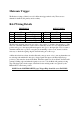
RA4 Wiring Details
INPUT PLUG OUTPUT PLUG
Pin Colour Wire Function Pin Colour Wire
Function
A BLUE Primary Trigger (-) A BLACK Ground
B WHITE Primary Trigger (+) B RED +12 Volts
C GREEN Secondary Trigger (+) C YELLOW Primary Trig
D GREY Secondary Trigger (-) D BROWN Secondary Trig
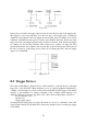
The Motronic magnetic sensor has two wires, one positive (+), and the other negative (-), The
wires are sometimes marked as such, but more often they are not. It is very important that the
positive wire goes to the input pin B and negative wire goes to the input pin A. If you can not
determine which wire is positive or negative from marking or wire colour, then it would be
necessary to check the signal going into the RA4 using an oscilloscope.
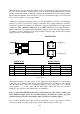
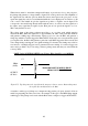
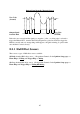
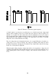
A Motronic wheel more than often has 60 teeth (some are more or less), among them there are
two missing teeth which will often give a larger signal. The input to the RA4 must first go
positive(+), this arms the circuit in the RA4. When the signal rises about 50 mV, the RA4 will
generate a falling edge and when the signal crosses zero volt, the RA4 will generate a rising
edge. The larger pulse in the output of the RA4 for the missing teeth is recognised by the
Haltech ECU as the home position.
NOTE: In the IGNITION SETUP page Trigger Edge should be set to FALLING.