
Manual


Model SC-DV-2
10
Reference Information
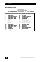
DVI Connector pinout N/U = Not Used
Pin Signal name Pin Signal name
1 TMDS Data2– 13 TMDS Data3+ (N/U)
2 TMDS Data2+ 14 +5V Power
3 TMDS Data2/4 Shield 15 Ground for +5V Power
4 TMDS Data4– (N/U) 16 Hot Plug Detect
5 TMDS Data4+ (N/U) 17 TMDS Data0–
6 DDC Clock 18 TMDS Data0+
7 DDC Data 19 TMDS Data0/5 Shield
8 Analog vertical sync 20 TMDS Data5– (N/U)
9 TMDS Data1– 21 TMDS Data5+ (N/U)
10 TMDS Data1+ 22 TMDS Clock Shield
11 TMDS Data1/3 Shield 23 TMDS Clock+
12 TMDS Data3– (N/U) 24 TMDS Clock–
C1 Analog red C4 Analog horizontal sync
C2 Analog green C5 Analog ground
C3 Analog blue