Skid and Trailer Installation, Operation and Service Maintenance Manual Hale Products Inc. ◆ A Unit of IDEX Corporation 700 Spring Mill Avenue ◆ Conshohocken, PA 19428 U.S.A. Telephone: 610-825-6300 ◆ FAX: 610-825-6440 Web......www.haleproducts.
NOTICE ! Hale Products, Inc. cannot assume responsibility for product failure resulting from improper maintenance or operation. Hale is responsible only to the limits stated in the product warranty. Product specifications contained in this manual are subject to change without notice. All Hale products are quality components -- ruggedly designed, accurately machined, precision inspected, carefully assembled and thoroughly tested.
Table of C ont ents ❑ Contents Page Skid and Trailer Installation, Operation and Service Hale Skid and Trailer Systems .............................................................................. 9 Figure A: Figure B: Figure C: Figure D: Figure E: Figure F: Figure G: 1 2 Model Number Breakdown .................................................................................... 9 Serial and Model Numbers ..................................................................................
❑ Ta ble of Contents Contents - continued Page 2a Accessories / Options............................................................................................. 27 2a.1 Anodes.............................................................................................................................. 27 Figure 2a-1: Hale 1-1/4” NPT Anode ....................................................................................... 27 2a.2 Auto-Start .........................................................
Table of C ont ents ❑ Contents - continued 3.4 Page Pumping Operations ........................................................................................................ 37 Initial Start Up ...................................................................................................................................37 Pumping Operations .........................................................................................................................38 Draft Operation Limiting Factors ...
❑ Ta ble of Contents Contents - continued 5 Page Troubleshooting - continued Pump ............................................................................................................................................. 47 Gearbox ......................................................................................................................................... 47 Accessories .........................................................................................................................
Table of C ont ents ❑ Contents - continued Page Appendix F: Cavitation ........................................................................................ 65 Figure F-1: Sample, Cavitation Regions ................................................................................ 65 Process of Cavitation ........................................................................................................................ 65 Warning Signs of Cavitation (Discharge and Gauges) ........................
❑ Ta ble of Contents Contents - continued Page Notes ________________________________________________________________ ________________________________________________________________ ________________________________________________________________ ________________________________________________________________ ________________________________________________________________ ________________________________________________________________ ________________________________________________________________ _
O ve rv iew ❑ Hale Skid and Trailer Systems Hale Products Inc. offers Engine-Driven Skid and Trailer Units that span a wide range of applications, from Marine unit to Industrial trailers, to meet the needs of Municipal, Government and Industrial customers. Skid and trailer units are ideal for permanent installation or for stand-by fire protection and offer the versatility, dependability, reliability, ease of operation and reduced maintenance that is so necessary to effective fire fighting.
❑ O ve rv iew When requesting for service or parts, it is important to provide the serial and model numbers of the equipment in question (engine, pump, etc.). For your convenience, fill in the information requested about your system. (See Figure B: “Serial and Model Numbers.”). It is then readily available when needed for identification purposes.
O ve rv iew ❑ Figure D: Typical - Cross-Chassis Non-Enclosed Skid Arrangement Overview - Skid & Trailer p/n: 029-0810-00-0 11
❑ O ve rv iew Figure E: Typical Tandem Trailer Arrangement 12 Overview - Skid & Trailer p/n: 029-0810-00-0
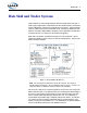
O ve rv iew ❑ Figure F: Typical - Skid / Trailer Control Panel Arrangement Overview - Skid & Trailer p/n: 029-0810-00-0 13
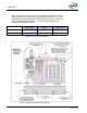
❑ O ve rv iew Figure G: Optional - Typical Skid / Trailer Electronic Governor Control Panel 14 Overview - Skid & Trailer p/n: 029-0810-00-0
❑ Saf ety 1 Safety Precautions IMPORTANT ! HALE FIRE SKIDS AND TRAILERS ARE DESIGNED FOR OPTIMUM SAFETY OF ITS OPERATORS. FOR ADDED PROTECTION, PLEASE FOLLOW THE SAFETY GUIDELINES LISTED IN THIS SECTION AND ADHERE TO ALL WARNING, DANGER, CAUTION AND IMPORTANT NOTES FOUND WITHIN THIS MANUAL. ALL SUPPLIED DOCUMENTATION (ENGINE, HALE PUMP, TRAILER MANUFACTURER’S MANUALS, ETC.
❑ Sa fet y 1.1 DEFINITIONS DANGER ! DANGER - Immediate hazard which WILL result in severe personal injury or death if the warning is ignored. WARNING ! WARNING - Hazards or unsafe practices which COULD result in severe personal injury or death if the warning is ignored. CAUTION ! CAUTION - Hazards or unsafe practices which COULD result in minor or moderate personal injury if the warning is ignored. NOTICE ! NOTICE - Practices which could result in damage to the apparatus or other property. 1.
Saf ety ❑ See separate documentation provided with the engine and pump and gearbox assemblies for proper fluids to use and quantities required. ❑ DO NOT permanently remove or alter any protective feature, guard or insulating devices, or attempt to operate the system when these guards are removed. Doing so voids the Hale warranty. Also see heading “Express Warranty” on page 69.
❑ Sa fet y ❑ When connecting the skid or trailer assembly to suction and / or discharge pipe lines, use only flexible connections. NEVER USE SOLID PIPE CONNECTIONS. If flexible couplings are used, follow the installation instructions furnished with the coupling. Certain flexible connections are subject to elongation under pressure, which imposes considerable strain to the pump. THESE SHOULD BE AVOIDED. ❑ DO NOT operate the system at pressures higher than the maximum rated pressure.
❑ Saf ety ❑ When mounting the skid assembly on a truck, trailer or other movable equipment, it is preferred to have the resting points under the skid frame as close as possible under the frame cross-members. This prevents undo strain on the frame and engine. ❑ When permanently mounting the skid assembly inside a building or a closed-in area, proper ventilation for engine cooling and engine exhaust must be provided.
❑ Sa fet y WARNINGS ! ❑ Adjust speed down (reduced) when towing a trailer. Driving too fast can result in loss of control and cause death or serious injury. ❑ ALSO SEE THE TRAILER MANUFACTURER’S MANUAL FOR SAFETY, CARE AND OPERATING INSTRUCTIONS. ❑ Refer to the laws / requirements provided by the authority having jurisdiction regarding connecting devices, safety chains, brakes, lighting and break-away systems on trailers.
❑ Saf ety WARNINGS - continued ! ❑ ❑ Incorrect rigging of the safety chain can result in loss of control of the trailer and tow vehicle leading to death or serious injury, if the trailer uncouples from the tow vehicle. Chains must: ● fasten to the tow vehicle, NOT to the hitch or ball. ● cross underneath the hitch and coupler with minimum slack to permit turning and to hold torque up, if the trailer comes loose.
❑ Sa fet y WARNINGS - continued ! 22 ● NEVER EXCEED THE TRAILER GROSS VEHICLE WEIGHT RATING (GVWR), AS NOTED ON THE V.I.N. PLATE. FAILURE TO COMPLY COULD RESULT IN SEVERE PERSONAL INJURY OR DEATH. ● NEVER load a trailer so that the weight on any tire exceeds the tire’s rating. ● NEVER exceed an axle Gross Axle Weight Rating (GAWR). ● NEVER exceed the rating of any of the hitch components. ● Proper tongue weight is essential for stable trailer handling.
Introduction 2 ❑ Introduction 2.1 SYSTEM COMPONENTS Hale skid or trailer units consist of: ❑ Hale Pump, with engine mount ❑ Diesel engine ❑ Gearbox (not on all units) ❑ Operator Control Panel (not on all units) ❑ Manifolding (not on all units) Hale Pump The Hale line of Centrifugal Pumps for engine driven systems (-M series) accept, adapter, #2, #3 and #4 SAE bell housings. Elastomeric drive discs are also available for 10” (254 mm) and 11.5” (292 mm) clutch discs.
❑ Introduction Skid (See Figure D: “Typical - Cross-Chassis Non-Enclosed Skid Arrangement,” on page 11.) Also see Figure E: “Typical Tandem Trailer Arrangement” on page 12. Hale skids are “customer design specific.” Various units offered are: ❑ Cross Chassis, Rail Mounted for trucks. ❑ Cross Chassis, Rail Mounted marine pumping units. ❑ Enclosed units, without Manifolds. ❑ Enclosed units, with Manifolds and Valving.
❑ Introduction Operator Control Panel, Typical (See Figure F: “Typical - Skid / Trailer Control Panel Arrangement,” on page 13.) Hale skid or trailer Operator Control Panels vary depended on customer order modifications and may differ from those displayed in this manual. Various components used in your system, such as the ENFO IV Engine Monitor, TPM Valving, SVS Valves, etc. offer their own Installation and Service manuals and are provided separately with your system.
❑ Introduction Engine Warning Light The engine warning light operates with the ENFO IV unit and illuminates to alert the operator of an engine related problem. Hour Meter The hour meter shows the operating time of the engine to assist with proper service intervals. Fuel Gauge The fuel gauge shows about how much fuel is in the tank. The gauge reads “E” when you first turn the ignition on. Then after a few seconds, it displays the proper fuel level.
❑ A cc es sorie s / O ptions 2a Accessories / Options The following accessories and /or options are available to complete a system installation: ❑ Anodes - see page 27. ❑ Auto-Start Systems - see page 28. ❑ Auxiliary Cooling, standard on some equipment - see page 28. ❑ Engine Governor Control - see page 29. ❑ Foam Proportioning Systems - see page 29. ❑ Pressure and Relief Valve Control - see page 30. ❑ Priming Systems - see page 32. ❑ Torrent Stainless Steel SVS Valves - see page 34. 2A.
❑ Ac ce ss orie s / O pt ions 2A.2 AUTO-START The auto-start push button, when pressed, starts the engine and the primer(s) to automatically prime the pump. The primer(s) shut-off when the pump is fully primed. Auto-start instructions are posted on a placard affixed to the unit. If your unit includes the auto-start system, for additional instructions, also see Section “Addendum” beginning on page 71. WARNING ! ALWAYS MAKE SURE THE KEY SWITCH IS SET TO “OFF” BEFORE SERVICING THE ENGINE.
A cc es sorie s / O ptions ❑ Figure 2a-3: Model “K” Heat Exchanger These units are used with any size radiator and use water from the pump to help maintain the proper temperature of the engine coolant during pumping. 2A.4 ENGINE GOVERNOR CONTROL, OPTIONAL The optional engine governor minimizes changes of pressure when volumes of water are changed. It is accomplished by changing engine speed to compensate from changes in pressure. (See Figure 2a-4: “Optional - Engine Governor Control.
❑ Ac ce ss orie s / O pt ions Hale FoamLogix Foam systems accurately deliver from 0.1% to 10.0% foam concentrate through a check valve / injector fitting, directly into the water discharge stream. It is then fed as foam solution into a standard fog nozzle, an air aspirated nozzle, or CAFS equipment, through the apparatus discharge piping.
A cc es sorie s / O ptions ❑ Thermal Relief Valves (TRV) Thermal Relief Valves (TRV) protect the pump from overheating and are mounted in the pump discharge. (See Figure 2a-7: “Thermal Relief Valve, TRV.”) The valve monitors the water temperature in the pump. When temperatures exceed 120° F (49° C), the valve automatically OPENS. When the temperature returns to a safe level, the valve CLOSES.
❑ Ac ce ss orie s / O pt ions WARNING ! TRV DISCHARGE WATER CAN BE “HOT!” BE CAREFUL TO AVOID BURNS. TRV-L Kit The TRV-L kit includes a chrome panel placard with a warning light, a light test button, and a pre-assembled wire harness. The RED light illuminates when the TRV is open and discharging water. (See Figure 2a-7: “Thermal Relief Valve, TRV,” on page 31.) An optional buzzer, mounted on the operator panel, provides an audible warning. 2A.
❑ A cc es sorie s / O ptions Priming Valves Hale priming valves open when the priming pump is operated to allow the air to escape from the pump. Two priming valves are offered: ❑ Hale Semi-Automatic Priming Valve (SPVR), for Remote Mounting A single push button on the operator’s panel starts the priming pump motor. When a vacuum is created, the SPVR OPENS. (See Figure 2a9: “SPVR Priming Valves.”) Releasing the push button stops the priming pump and the SPVR CLOSES.
❑ Ac ce ss orie s / O pt ions 2A.8 TORRENT SVS VALVES Torrent SVS valves control the flow to and from the full range of Hale pumps. SVS valves enable the operator to shut off flow completely, or throttle the flow rate from a trickle to full flow. (See Figure 2a-11: “SVS Valve Primary Components.”) Numerous adapters tailor the valve to almost any installation requirement.
Operation 3 ❑ Basic Operation WARNING ! THE PROCEDURES IN THIS SECTION ARE GENERAL OPERATING PROCEDURES. NOT ALL PROCEDURES IN THIS SECTION MAY APPLY TO YOUR SPECIFIC OPERATIONAL REQUIREMENTS. REFER TO ONLY THOSE SECTIONS WHICH APPLY TO YOUR OPERATIONAL REQUIREMENTS. THESE PROCEDURES DO NOT REPLACE THE PROCEDURES, POLICIES OR GUIDELINES ESTABLISHED BY THE AUTHORITY HAVING JURISDICTION.
❑ Operation IMPORTANT ! AT INSTALLATION AND BEFORE OPERATION, ALL FLUIDS MUST BE ADDED PER THE MANUFACTURER’S REQUIREMENTS AND TO THE APPROPRIATE LEVELS. SEE SEPARATE DOCUMENTATION PROVIDED WITH THE ENGINE AND PUMP AND GEARBOX ASSEMBLIES FOR PROPER FLUIDS TO USE AND QUANTITIES REQUIRED. Before operation, refill - 3.3 ❑ Engine crankcase OIL. ❑ Engine WATER coolant (anti-freeze). ❑ Engine battery fluid (ELECTROLYTE). ❑ Pump and gearbox OIL.
O peration ❑ ❑ Safety break away switch cable is fastened to the tow vehicle, not to the safety chain. ❑ Tires are inspected ● Pressure - check when cold ● Tread and wear patterns. ● Cuts. bulges, cracks and visible cords. ❑ Wheels - Cracks, dents, and bends. ❑ Lug nuts are tight. ❑ Test lights for proper operation - Tail, Stop and Turn. ❑ Cargo appropriately restrained and evenly distributed. ❑ Fire extinguisher. ❑ Flares and reflectors.
❑ Operation Pumping Operations 1. Position the skid or trailer as close to the water source as practical. Pumps smaller than 1,500 GPM (5,678 LPM) can draw 100% of rated capacity with less than 10 feet (3.05 meters) vertical lift and 20 feet (6 meters) of suction hose. Pumps smaller than 3,000 GPM (11,356 LPM) have six (6) feet (1.8 meter) vertical lift capability. As the vertical lift increases, pump capacity is reduced. (See Figure F-3: “Lift Loss from Elevation” on page 67.
❑ O peration CAUTION - continued ! STOP THE PUMP AND CHECK FOR AIR LEAKS OR POSSIBLE PROBLEMS. SEE SECTION 5 “TROUBLESHOOTING,” ON PAGE 47. 9. When operating from a positive pressure source (e.g. hydrant or relay), make sure any air is purged from the hose and pump. CAUTION ! WHEN OPERATING FROM A POSITIVE PRESSURE SOURCE WITH A SOFT SUPPLY HOSE, DO NOT DRAW RESIDUAL PRESSURE BELOW 5 PSI (0.4 BAR) OR YOUR DEPARTMENTAL LIMITS. DAMAGE TO THE HYDRANT, HOSE AND POSSIBLY THE PUMP MAY RESULT. 10.
❑ Operation ❑ Air enters with the water - Air leaks can cause rough operation and an increase in engine speed without an increase in pressure or flow. If an air leak is suspected, discontinue pumping - see heading “Troubleshooting” on page 47. ❑ Hot water - see Figure F-2: “Lift Loss from Temperature” on page 67. ❑ Low barometer - see Figure F-3a: “Lift Loss from Barometric Reading” on page 67. ❑ High lift - see Figure F-3: “Lift Loss from Elevation” on page 67.
❑ O peration 3.5 RELIEF VALVE PROCEDURES Be sure to select the correct procedure based on how the skid or trailer is equipped. (See Figure 3-1: “TPM / PMD Relief Valve Control” on page 41.) Some engines may utilize a governor in place of the relief valve. Standard Relief Valve Procedures 1. Increase the engine RPM to the desired pump operating pressure while reading the discharge pressure gauge. 2. Turn the handwheel slowly counterclockwise until the relief valve opens.
❑ Operation 5. When the pump is not in operation, turn the handwheel clockwise to a position slightly above the normal operating pressure. More complete and detailed information is found in the relief valve manual. CAUTION ! THE PRESSURE INDICATOR ON THE PANEL IS ONLY A ROUGH INDICATION OF TPM SETTING. ALWAYS USE THE PRECEDING PROCEDURE TO PROPERLY SET THE TPM RELIEF VALVE SYSTEM. 3.6 42 POST OPERATION PROCEDURES 1. Return the engine to IDLE, then slowly close all valves. 2.
❑ Prev entive Mainte nance 4 Preventive Maintenance 4.1 OVERVIEW Hale skids and trailers require very little care and maintenance. However, the little required is extremely important. Preventive maintenance tasks require very little time to accomplish and consist mainly of testing for leaks, lubrication, and cleaning. Always follow local / departmental maintenance and test procedures.
❑ Prev entiv e Mainte nance 4.2 POST OPERATION Fluids Before operation, check and refill ❑ Engine crankcase OIL. ❑ Engine WATER coolant (anti-freeze). ❑ Engine battery fluid (ELECTROLYTE). ❑ Pump and gearbox OIL. General Review Visual Inspection Visually inspect the base frame (e.g. cross-chassis, trailer, etc.), engine compartment, manifolds and valves, and pump and gearbox assemblies.
❑ Prev entive Mainte nance See manufacturer’s documentation for maintenance inspection intervals, fluid type and requirements. ❑ Check brakes for proper operation. Any problems with the brakes must be repaired immediately. Do not use the trailer. Electrical ❑ Inspect electrical cable harnesses to ensure they are in good condition and that all connectors are correctly assembled and secured - repair and / or replace accordingly. Operate tail lights and turn signals and observe for proper operation.
❑ Prev entiv e Mainte nance Any problems with the preceding items must be repaired immediately. Do not use the trailer. During Operation ❑ Be alert for unusual noises or improper operation of system equipment, e.g. brakes, stabilizer jacks, etc. ❑ Investigate and correct or report any faults noted during operation. ❑ Inspect suspension and associated mounting parts for damage. Repair and / or replace accordingly.
❑ Troubles hooting 5 Troubleshooting 5.1 OVERVIEW Troubleshooting symptoms, possible causes and suggested corrective action / remedies are discussed in the various manufacturer’s documentation. For Troubleshooting Engine See the engine manufacturer’s documentation, supplied with your unit. Trailer See the trailer manufacturer’s documentation, supplied with your unit, for the trailer assembly, axle, brake system, tires, etc.
❑ Troubles hooting Notes ______________________________________________________________ ______________________________________________________________ ______________________________________________________________ ______________________________________________________________ ______________________________________________________________ ______________________________________________________________ ______________________________________________________________ _____________________________________________
Insta llation 6 ❑ Installation 6.1 OVERVIEW This section provides general guidelines and recommendations for positioning or permanently installing the skid pumping system. For permanent installation inside buildings, care must be taken to provide proper ventilation for engine coolant and to prevent accumulation of exhaust gases. Exhaust gases contain carbon monoxide, an odorless and deadly poison.
❑ Insta llation Figure 6-1: Recommended Permanent Installation 2. Install foundation bolts and pour soft concrete to the required depth below the skid base frame. 3. After the concrete has hardened, set the skid unit in place and level the unit using the appropriate shims. 4. Tighten the foundation bolts. INOTICE ! CARE MUST BE TAKEN TO ELIMINATE ANY STRAIN ON THE SKID FRAME DUE TO AN UNEVEN FOUNDATION. ADD SHIMS ACCORDINGLY.
❑ Insta llation ❑ The suction line should be laid either exactly horizontal, or with a uniform slope upward from the water supply to the pump. Avoid high spots or "air traps." Air which collects at the high spots may be carried into the pump, causing loss of prime, and must be scavenged with the priming pump. ❑ To avoid excessive friction loss, the discharge pipe must be sized accord- ingly.
❑ Insta llation Check if any parts are missing or have been damaged during shipment. If any damage is noticed, note such damage on your bill of lading and request the delivery agent to sign it. Immediately report any damage to your dealer and shipping agent. General ❑ Engine - Check that all points requiring lubrication are properly lubri- cated in accordance with the manufacturer’s supplied engine manual.
G loss ar y a nd Mea surem ents ❑ Appendix A: Glossary Atmospheric .......Pressure caused by the elevation of air above the earth. Atmospheric pressure is 14 Pressure .............pounds per square inch at sea level. Pressure increases below sea level and decreases above sea level. The weather also effects atmospheric pressure. Atmospheric pressure effects a pumps ability to pump from draft. Higher pressures increase a pumps performance, while lower pressures can cause a noticeable decrease in lift.
❑ Glos sa ry and Mea sureme nts WARNING ! IF A PUMP IS OPERATED WITHOUT WATER FOR EXTENDED PERIODS, OR WITHOUT DISCHARGING WATER, IT MAY OVERHEAT. THIS COULD DAMAGE THE MECHANICAL SEAL OR THE DRIVE MECHANISM. Double Suction ..Fluid enters on both sides of the impeller. Impeller Dry Prime Test ...Provides information on the ability of a priming pump to evacuate air from the main pump. If the vacuum does not hold, it is an indication there is a leak in the system. Flow Meter ..........
G loss ar y a nd Mea surem ents ❑ Positive ..............Pressure above atmospheric. Pressure Power Valve........A valve that uses hydraulic pressure to transfer two-stage pump operation from volume mode to pressure mode, and vice versa. Pressure .............Force per unit area. Pressure ............The pressure gauge is usually graduated in pounds per square inch (PSI) only. It Gauge is connected to the pump discharge manifold, thus indicating pump discharge ressure. Priming ...............
❑ Glos sa ry and Mea sureme nts Stages .................The number of impellers in a pump that are used in series; that is, one following another in terms of flow. Each impeller develops part of the total pump pressure. Tachometer ........Indicates the speed of the engine crankshaft in revolutions per minute. Torque.................The force that acts to produce rotation. Transfer Valve ...
G loss ar y a nd Mea surem ents ❑ Appendix A-1: Measurements Water Horsepower ........................................................................................................ (GPM x PSI)/1,714 One Gallon of Water Weighs ..................................................................................................8.33 Pounds One Gallon...................................................................................................................... 231 Cubic Inches One Cubic Foot.............
❑ Glos sa ry and Mea sureme nts Hale Products Inc. A Unit of IDEX Corporation 700 Spring Mill Avenue Conshohocken, PA 19428 U.S.A. Telephone..............1-610-825-6300 Fax ........................1-610-825-6440 Web ........ www.haleproducts.com 58 Appendix A: Glossary / Measurements Hale Products, Inc., July 2006, Rev.
A lternate Lubrica nt Manufac ture rs ❑ Appendix C: Alternate Lubricant Manufacturers In addition to the Hale recommended lubricants: ❑ FULL SYNTHETIC SAE 50 Transmission Lubricant (Cognis 2924/2833) ❑ DEXRON III SYNTHETIC (Cognis 2803) for temperatures below 32°F (0°C) the following list of alternate oils and suppliers is provided . Oil / Lubricant Manufacturer Alternate STANDARD-Temperature Lubricant (Cognis 2923/2833) See Service Manual for additional information.
❑ Alt erna te Lubric ant Ma nufa ct urers Oil / Lubricant Manufacturer Alternate STANDARD-Temperature Lubricant (Cognis 2923/2833) See Service Manual for additional information. Monarch Syntran Plus SAE-50 Trans. Royal Manufacturing Company, Inc. P O Box 3308 516 South 25th West Avenue Tulsa, OK 75127 Mystik Synguard SX-7000 SAE-50 Trans. Cato Oil and Grease Company P O Box 26868 1808 NE 9th Street Oklahoma City, OK 73126 Peterbilt SAE-50 Original Factory Fill Fluid, Trans.
❑ Lubric ant Spe cific ations Appendix C1: Lube and Sealant Specifications Approximate Capacity Pump Gearbox Recommended Oil Quarts Liters 5 4.7 SAE 50 - above 0° F (above -18° C); Dextron III or Cognis 2803 - between -40°F to 0°F (-40° to -18°C) 2 1.9 SAE 50 80W-90; 75W-80 Synthetic B (Horizontal) 1.5 1.4 SAE 50 80W-90; 75W-80 Synthetic 4DK APS APSM MBP MBPM 4DB SBP B (Vertical) B (Inverted) 1.75 1.
❑ Lubric ant Spe cific ations Pump Gearbox Approximate Capacity Recommended Oil Quarts Liters APM / AP / CBP 2CBP / CBP2 / CBP3 2CBP2 / 2CBP3 1.75 1.7 SAE EP90 80W-90; 75W-140 Synthetic (Lubricants must meet service rating API GL-5.) 20FS 30FS 1.75 1.7 SAE EP90 80W-90; 75W-140 Synthetic (Lubricants must meet service rating API GL-5.) 3 2.8 SAE EP90 80W-90; 75W-140 Synthetic (Lubricants must meet service rating API GL-5.
❑ Hos e Fric tion Loss 2.0” (38) Hose with 1-1/2” (38mm) Coupling GPM (LPM) 3-1/2” (89mm) Hose 4.0” (102mm) Hose 14 (0.96) 8 (0.6) 500 (1,893) 9.5 (0.7) 3 (0.2) 20 (76) 44 (3.0) 6 (0.4) 125 (473) 24 (1.7) 13 (0.9) 750 (2,839) 20 (1.4) 11 (0.8) 5 (0.4) 30 (114) 99 (6.8) 14 (0.96) 150 (568) 35 (2.4) 18 (1.2) 1,000 (3,785) 34 (2.4) 20 (1.4) 8 (0.6) 40 (151) 176 (12.0) 24 (1.7) 4 (0.3) 175 (662) 47 (3.2) 25 (1.7) 6 (0.4) 1,250 (4,732) 53 (3.7) 31 (2.1) 13 (0.
❑ Hos e Fric tion Loss Hale Products Inc. A Unit of IDEX Corporation 700 Spring Mill Avenue Conshohocken, PA 19428 U.S.A. Telephone ..............1-610-825-6300 Fax.........................1-610-825-6440 Web ........ www.haleproducts.com 64 Appendix D: Hose Friction Loss Hale Products, Inc.
❑ C av it ation Appendix F: Cavitation (See Figure F-1: “Sample, Cavitation Regions.”) Cavitation can occur while pumping from draft, in relay, or from a hydrant (although it is more likely from draft conditions). The operator must be aware of the warning signs and immediately correct the situation. Cavitation can damage the impeller and other sensitive components, impair pump performance, and reduce flow capacity.
❑ Ca vit ation This sudden change from vapor to liquid generates a shock effect that damages the impeller and pump housing. Usually there are thousands of tiny vapor pockets (or bubbles). It is the collapsing (or implosion) of these bubbles that causes the characteristic sound of cavitation that has been described as rocks tumbling in the pump.
❑ C av it ation During Operations Water Temperature F° (C°) Lift Losses Head Ft. (Meters) ❑ Do not increase pump speed NFPA Base Line - 2.38 (0.73mm) 60° (16°) beyond the speed at which 70° (21°) 0.3 (0.09) the pressure ceases to rise. The higher the elevation 80° (27°) 0.6 (0.18) above sea level, the lower 90° (32°) 1.1 (0.34) the atmospheric pressure 100° (38°) 1.7 (0.52) and less lift. Lift loss is in (43°) 110° 2.5 (0.76) addition to NFPA Baseline of 2.38 ft. (0.
❑ Ca vit ation ❑ Consider the piping within the truck. Suction losses can result from additional suction piping added to the fire pump during assembly. Hose Diameter in. (mm) 3” (76) 4” (102) Flow - gpm (lpm) 250 (946) 6” (152) Dual 6” (152) 5.2 (20) 2.5 (9.5) 500 (1,893) 5.0 (19) 750 2,839) 11.4 (43) 1,250 (4,732) 5” (127) Lift Loss (gpm (lpm) 350 (1,325) 1,000 (3,785) 4.5” (127) 3.6 (13.6) 8.0 (30) 4.7 (18 1.9 (7.2) 14.5 (55) 8.5 (32) 3.4 (13) 13 (49) 5.2 (20) 1,500 (5,678) 7.
Limite d W arra nty Express Warranty EXPRESS WARRANTY: Hale Products, Inc. (HALE) hereby warrants to the original Buyer that products manufactured by Hale are free of defects in material and workmanship for two (2) years or 2,000 hours usage, whichever shall first occur. The “Warranty Period” commences on the date the original Buyer takes delivery of the product from the manufacturer.
Hale Products Inc. A Unit of IDEX Corporation 700 Spring Mill Avenue Conshohocken, PA 19428 U.S.A. Telephone..............1-610-825-6300 Fax ........................1-610-825-6440 Web ........ www.haleproducts.
Addendum ❑ Addendum THIS SKID OR TRAILER SYSTEM IS BUILT TO SPECIFIC CUSTOMER REQUIREMENTS. IN ADDITION TO THE INFORMATION PROVIDED PRIOR TO THIS SECTION AND THE COMPONENT MANUALS / DOCUMENTATION PROVIDED UNDER SEPARATE COVER, THE ADDENDUMS LOCATED BEHIND THIS PAGE MUST BE CAREFULLY READ, UNDERSTOOD AND ADHERED TO STRICTLY BY ALL INSTALLERS AND OPERATORS BEFORE ATTEMPTING TO INSTALL OR OPERATE THE SKID OR TRAILER PUMPING SYSTEM.
❑ Addendum Notes ______________________________________________________________________ ______________________________________________________________________ ______________________________________________________________________ ______________________________________________________________________ ______________________________________________________________________ ______________________________________________________________________ ____________________________________________________________________
Skid and Trailer Drawing Package Hale Products Inc. ◆ A Unit of IDEX Corporation 700 Spring Mill Avenue ◆ Conshohocken, PA 19428 U.S.A. Telephone: 610-825-6300 ◆ FAX: 610-825-6440 Web........www.haleproducts.
Contents 7 Drawings Customer Specific Installation / Layout Plate Drawings Manual p/n: 029-0810-00-0, Rev. -A Printed in U.S.A. © Hale Products, Inc.