09/16/96 MGA and RGA SERIES SPLIT-SHAFT PTO DRIVE GEARBOX INSTALLATION MANUAL All Hale products are quality components: ruggedly designed, accurately machined, precision inspected, carefully assembled and thoroughly tested. In order to maintain the high quality of your unit, and to keep it in a ready condition, it is important to follow the instructions on care and operation. Proper use and good preventive maintenance will lengthen the life of your unit.
SPLIT-SHAFT PTO GEARBOX TABLE OF CONTENTS Section Page 1 SAFETY ................................................................................................................... 1 2 DESCRIPTION ......................................................................................................... 2 3 DRIVE LINE INSTALLATION PLANNING ................................................................ 8 4 INSTALLATION .........................................................................................
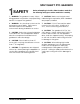
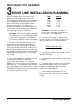
SPLIT-SHAFT PTO GEARBOX SAFETY Before attempting to install a Hale Gearbox, read all of the following safety precautions and follow carefully. 1. WARNING: The gearbox is heavy. When lifting gearbox into position use proper lifting devices to support the gearbox. 6. CAUTION: Make sure interlocks and indicator lights required by NFPA standards are properly installed. 2. WARNING: Any electrical system has the potential to cause sparks.
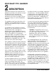
SPLIT-SHAFT PTO GEARBOX DESCRIPTION Hale MGA and RGA Series Split-Shaft PTO gearboxes provide a cost effective means for driving a pump, generator, air compressor, winch or other auxiliary equipment from the truck engine without resorting to high cost, heavy, dedicated engines. can drive two pieces of auxiliary equipment simultaneously. The MGA gearbox can be configured with the auxiliary drive shaft positioned with either spline facing in either the front or rear position.
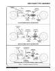
SPLIT-SHAFT PTO GEARBOX APPARATUS ENGINE AUXILIARY DRIVE SHAFT APPARATUS TRANSMISSION RGA GEARBOX FRONT DRIVE SHAFT SECTION REAR DRIVE SHAFT SECTION RGA GEARBOX DRIVE LINE MOUNTED APPARATUS ENGINE AUXILIARY DRIVE SHAFT APPARATUS TRANSMISSION FRONT DRIVE SHAFT SECTION MGA GEARBOX REAR DRIVE SHAFT SECTION MGA GEARBOX DRIVE LINE MOUNTED APPARATUS ENGINE TRANSMISSION MOUNTED PTO AUXILIARY DRIVE SHAFT GEARBOX DRIVE SHAFT MGA GEARBOX APPARATUS DRIVE SHAFT APPARATUS TRANSMISSION TRANSMISSION PTO DR
SPLIT-SHAFT PTO GEARBOX CAUTION: When driving high inertia auxiliary equipment such as a generator, make sure the equipment shaft stops rotating before shifting back to ROAD position. Shifting to road position before the shaft stops turning will result in damage to gears. The gearbox is shifted back to road position by placing the apparatus transmission in neutral and waiting until auxiliary component shaft has stopped turning.
SPLIT-SHAFT PTO GEARBOX consult with Hale Products to determine gearbox cooler requirements. Cooling water for the gearbox cooler is provided from the fire pump discharge or the apparatus engine cooling system. The RGA Series Split-Shaft gearbox is available with five different gear ratios to provide a wide range of output speeds from a large variety of engine and transmission combinations. The available RGA models and ratios are as follows: MODEL RATIO RGA-23 2.28:1 RGA-21 2.05:1 RGA-19 1.
SPLIT-SHAFT PTO GEARBOX SPECIFICATIONS: RGA MGA Final Drive Ratios Available: 1.58:1, 1.71:1, 1.86:1, 2.05:1, 2.28:1 3.00:1, 2.67:1, 2.18:1, 1.92:1, 1.71:1, 1.27:1, 1.
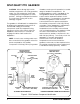
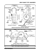
SPLIT-SHAFT PTO GEARBOX GEARBOX MOUNTING HOLES (5/8-11 UNC x 1 INCH DEEP) GEARBOX MOUNTING HOLES (5/8-11 UNC x 1 INCH DEEP) AUXILIARY DRIVE SHAFT (1-3/8 INCH x 10 SPLINE) AUXILIARY DRIVE SHAFT (1-½ INCH x 10 SPLINE) SERIAL NUMBER PLATE SERIAL NUMBER LOCATION AIR VENT OPTIONAL SPEED COUNTER OIL FILL AND LEVEL PLUG REAR DRIVE FLANGE FRONT DRIVE FLANGE OIL DRAIN PLUG SHIFTING SHAFT GEARBOX MOUNTING HOLES (5/8-11 UNC x 1 INCH DEEP) TO FRONT OF APPARATUS OPTIONAL GEARBOX COOLER GEARBOX MOUNTING HO
SPLIT-SHAFT PTO GEARBOX DRIVE LINE INSTALLATION PLANNING Before installing either the MGA or RGA gearbox careful planning is necessary. When planning the layout for the installation of the gearbox careful attention must be given to all factors that will affect total system performance. To reduce the possibility of drive line failure, proper layout is necessary.
SPLIT-SHAFT PTO GEARBOX INSTALLATION WARNING: The gearbox is heavy. When lifting gearbox into position use proper lifting devices to support the gearbox. NOTE: Lock all bolts in place using Loctite #242 (or equal) thread sealing compound. 1. Fabricate brackets and attach to apparatus frame at the location where the gearbox is being mounted.
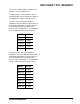
SPLIT-SHAFT PTO GEARBOX 5 1-½ IN x 10 SPLINE /8-11 UNC x 1 IN. DEEP (TYP.) 1-3/8 IN x 10 SPLINE A B 19 IN. (483 mm) C 3-¼ IN. (83 mm) 5-1/8 IN. (133 mm) D 14- 7/16 IN. (367 mm) E E 11- 1/8 IN. (283 mm) 5-¾ IN. (146 mm) 13 IN. (330 mm) 11- 9/16 IN.
SPLIT-SHAFT PTO GEARBOX matter. Either end of the gearbox cooler can be selected as the water inlet. Gearbox Oil Capacity: RGA (All Models) ....... 8 pints (3.8 liters) MGA: Vertical: MGA-30, MGA-26, MGA-21, MGA-19, MGA17 ................... 5-½ pints (2.6 liters) MGA-12, MGA-10 . 7 pints (3.3 liters) Horizontal: All Models .............. 6 pints (2.8 liters) NOTE: Cooling water must be connected to the gearbox when the power required for the auxiliary component is 200 hp (149 kw) or greater. 9.
SPLIT-SHAFT PTO GEARBOX pressure of 500 PSI (34 BAR), from the water pump discharge to the gearbox cooler inlet fitting. CAUTION: Make sure interlocks and indicator lights required by NFPA standards are properly installed. 10. Connect 3/8 inch (10 mm) diameter tube, with minimum working pressure of 500 PSI (34 BAR), from the gearbox cooler outlet fitting to the water pump suction. WARNING: Any electrical system has the potential to cause sparks.
SPLIT-SHAFT PTO GEARBOX POWER CONNECTION FOR “PUMP ENGAGED” INDICATOR LIGHT (+12 VDC) IMPORTANT: ALL INSTALLER SUPPLIED WIRE SHALL BE MINIMUM 14 AWG TYPE SXL OR GXL (SAE J1128) MATING CONNECTOR (PROVIDED BY INSTALLER) PACKARD WEATHERPACK TERMINAL NO: ..................... 12010085 CONNECTOR NO: ................. 12010973 SEAL NO: ..............................