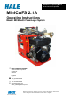
MiniCAFS 2.1A Operating Manual GP/211/05 Issue 2. April 2005 MiniCAFS 2.1A Operating Instructions Model: MC50 with FoamLogix System HALE PRODUCTS EUROPE A Unit of IDEX Corporation Charles St Warwick CV34 5LR England +44 (0)1926 623600 ¬ +44 (0)1926 623666 www.haleeurope.com admin_haleuk@idexcorp.com 1 ©Hale Products Europe. Our policy is one of continuous development. We therefore reserve the right to amend specifications without notice or obligation.
MiniCAFS 2.1A Operating Manual GP/211/05 Issue 2.
MiniCAFS 2.1A Operating Manual GP/211/05 Issue 2. April 2005 IMPORTANT NOTES Please read this manual before operating this equipment. Every care has been taken during the manufacture of this equipment to ensure that it leaves the factory capable of giving a long period of trouble-free running. 3 ©Hale Products Europe. Our policy is one of continuous development. We therefore reserve the right to amend specifications without notice or obligation.
MiniCAFS 2.1A Operating Manual GP/211/05 Issue 2. April 2005 SAFETY - RELEVANT DATA Thank you for purchasing a MiniCAFS unit. MiniCAFS is designed to give safe and reliable service – however, BEFORE operation it is essential that the Operating Instructions are carefully read and understood.
MiniCAFS 2.1A Operating Manual GP/211/05 Issue 2. April 2005 MANUAL HANDLING If the unit is to be removed from the appliance the design incorporates suitable lifting points. The secondary starting method (hand-start) provided MUST BE USED WITH CARE. Follow the operating instructions provided. ENVIRONMENTAL PROTECTION It is illegal to pour engine oil and other contaminants onto the ground, down sewers or drains, or into water courses.
MiniCAFS 2.1A Operating Manual GP/211/05 Issue 2. April 2005 GENERAL DATA ENGINE Manufacture Model Bore & Stroke Capacity Number of cylinders Number of main bearings Lubrication Pressurised Service Oil Fill Capacity Oil filter Fuel feed Fuel tank capacity Battery Briggs & Stratton 18HP Vanguard 72.5mm x 70mm 570 cc 2 cyl vee 2 Full Flow System 1.7 litres 'Spin On' disposable canister Vacuum Pulse Pump 8.
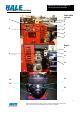
MiniCAFS 2.1A Operating Manual GP/211/05 Issue 2. April 2005 INSTRUMENTS and CONTROLS 1 Foam/CAFS controls 17 3 4 2 5 6 7 Engine 8 10 9 11 12 13 14 15 16 7 ©Hale Products Europe. Our policy is one of continuous development. We therefore reserve the right to amend specifications without notice or obligation.
MiniCAFS 2.1A Operating Manual GP/211/05 Issue 2. April 2005 INSTRUMENTS 1. WET or DRY foam selector COMMENTS Press top to make foam wetter Press bottom to make foam dryer 2. FoamLogix display and control See page 16 for details 3. CAFS or Foam selector Press top for CAFS, press bottom for foam only 4. Hours run counter Records total number of hours engine has been running 5. Air dump valve Rapid relief of compressor pressure to aid cold starting 6.
MiniCAFS 2.1A Operating Manual GP/211/05 Issue 2. April 2005 INTRODUCTION The MiniCAFS is a Compressed Air Foam System comprising of three major components – air compressor (driven by air-cooled engine), FoamLogix (foam proportioning unit) and manifold (foam mixing and control system). All the components are in one integrated module designed to fit in the standard envelope of a DIN 8kVA generator.
MiniCAFS 2.1A Operating Manual GP/211/05 Issue 2. April 2005 FoamLogix The FoamLogix 2.1 foam proportioning system consists of three main components: 1) Foam Pump / Motor Assembly, mounted on top of the unit. 2) Control Panel, mounted on the side of the unit. 3) Flow measurement and injection manifold, mounted on top of the unit. All three parts work together to provide accurate and reliable foam proportioning.
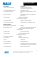
MiniCAFS 2.1A Operating Manual GP/211/05 Issue 2. April 2005 INSTALLATION Caution: MiniCAFS is shipped without oil in the Compressor or Engine. Oil MUST be added before the unit is started. All connections are labelled and must be secured before starting the unit. A C D B E G F H K J 11 ©Hale Products Europe. Our policy is one of continuous development. We therefore reserve the right to amend specifications without notice or obligation.
MiniCAFS 2.1A Operating Manual GP/211/05 Issue 2. April 2005 1. If the unit is installed in the side locker of a fire fighting vehicle, provision must be made for access to the engine oil dipstick (A), compressor oil-fill (B) and sight glass (D), all located on the rear side of the MiniCAFS. The drive motor is air-cooled, and cooling air must be allowed to flow unhindered into and out of the unit. Avoid any enclosing cladding at a distance of approx. 300mm around the engine cooling air intake.
MiniCAFS 2.1A Operating Manual GP/211/05 Issue 2. April 2005 5. Connect a water supply of 4-10 bar pressure from the main pump to the inlet connection on the MiniCAFS manifold. This should be of φ50, flexible, non-kinking hose. An isolating valve must be provided between the vehicle pump and the MiniCAFS unit to prevent the unit being pressurised when not being used. 6. Fill the engine with engine oil & fuel as per the Briggs & Stratton manual. 7.
MiniCAFS 2.1A Operating Manual GP/211/05 Issue 2. April 2005 COMMISSIONING/ START-UP PROCEDURE Caution: The heat exchanger return flow is over 40 l/min. This flow must not be restricted. Caution: The unit should be run in open air with any compartment doors open and the containment drawer ideally pulled out to improve ambient airflow. 1. Follow the installation procedure in the previous section. 2. Supply the MiniCAFS with water at a pressure of 4-10 BAR. 3.
MiniCAFS 2.1A Operating Manual GP/211/05 Issue 2. April 2005 FoamLogix control panel functions - Check that all the necessary connections have been made as described in the previous sections 1. Run the compressor for 30 seconds to allow oil to circulate. Press the CAFS switch (3, P8) on the instrument section. 2. Stop the unit and check compressor oil level – top up if necessary. 3.
MiniCAFS 2.1A Operating Manual GP/211/05 Issue 2. April 2005 ”no Pr” = No prime display 7. When prime is achieved, deselect simulated flow by pressing both up ↑ & down ↓ at the same time. 8. Return the bypass valve to the inject position (arrow points to right). The unit is now ready to run. OPERATING MiniCAFS FROM A VEHICLE WATER SOURCE 1. Connect a suitable delivery hose and branch to the CAFS discharge. φ38 to φ45mm diameter layflat hose is suitable for delivering compressed air foam.
MiniCAFS 2.1A Operating Manual GP/211/05 Issue 2. April 2005 FoamLogix Control Panel 1. Discharging foam agent only 1.1. Set water feed from supply pump at required pressure 1.2. Ensure that the foam only option is selected by pressing the bottom of the Foam/CAFS selector switch, marked with the symbol (No.3, Page 7) 1.3. Press the red on button, and choose desired foam % setting. (Default is 0.5%) Foam % Press ↑ to increase foam % Press ↓ to decrease foam % 1.4.
MiniCAFS 2.1A Operating Manual GP/211/05 Issue 2. April 2005 Wet Foam or Dry Foam 2.4. A continuously variable foam type from WET to DRY is available, selectable by the pump operator. 2.5. The WET or DRY foam composition is selected by using the WET/DRY control on the panel (No.1 Page 7). An indication of foam type is given by the WET or DRY foam indicator (No.7 Page 7), but the pump operator may choose to optimise the liquid flow as displayed in the FoamLogix display. 2.6.
MiniCAFS 2.1A Operating Manual GP/211/05 Issue 2. April 2005 TO OPERATE FROM A REMOTE FOAM SUPPLY Foam agent can be inducted out of conventional commercial canisters. The base of the canisters must be above the FoamLogix Pump and the MiniCAFS. A suitable dip tube should be manufactured for the suction line. The bypass pipe should be fed back into the foam canister. Note The FoamLogix must be re-primed each time the foam canister is changed.
MiniCAFS 2.1A Operating Manual GP/211/05 Issue 2. April 2005 MAINTENANCE Weekly: Check the oil levels and top up if necessary. Check the belt tension/condition and adjust if necessary. Check the hose connections. Check battery charge. Every 50 hours or every 3 months Check and clean the water supply filter (M, Page 12) for debris Every 100 hours or every 6 months (whichever comes first): Change the engine oil and filter. B&S oil filter P/N 4929325 Change compressor oil and filter.
MiniCAFS 2.1A Operating Manual GP/211/05 Issue 2. April 2005 FAULT FINDING EFFECT Compressor overheats CAUSE No water supply or restricted flow ACTION Turn on water supply.
MiniCAFS 2.1A Operating Manual GP/211/05 Issue 2. April 2005 RECOMMENDED FOAM AGENTS Class A Foam US Forestry Service Approved Manufacturer ANSUL Angus Chubb National Foam Chubb National Foam Monsanto Chemonics Chemonics 3M ChemGuard Unifoam Co Ltd. 3M Non U.S. Forestry Service Approved Brand name Silvex Class A Foam Concentrate Forexpan S (0.1% - 1.