Manual
Manuals
Brands
Hale Manuals
Equipment
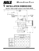
Master Intake Valve
31
32
33
34
35
36
37
38
39
40
32
M
ASTER
I
NT
AKE
V
AL
VE
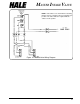
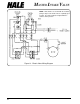
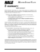
Figure 13.
Electric
V
alv
e Wiring Diagram
NOTE:
Limit switches are shown with the actuating
plungers depressed and the valve in a partially open
position.
The amber indicator is lighted with the
switches in this position.
1
...
...
32
33
34
35
36
...
...
46