
Manual

26
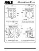
MASTER INTAKE VALVE
WARNING: The relief valve spring is
under pressure and can cause a
projectile hazard. When disassembling
the relief valve, back relief valve
adjustment screw out to lowest setting to
relieve pressure on spring before
removing relief valve housing screws.
4. Using a
3
/16 inch Allen wrench remove
the pressure adjustment cap screw
locking screw.
5. Using a
7
/8 inch open end wrench,
remove the pressure adjustment cap
screw to relieve pressure on the
adjustment spring.
6. Usinga¼inchAllen wrench remove the
four
3
/8-16 x
7
/8 inch long socket head
cap screws that hold the valve bonnet
to the end cap.
7. Remove the piston, coil spring and
tension washer from inside the valve
bonnet.
8. Remove the adjustment bushing from
the valve bonnet.
9. Clean and inspect all components and
replace those that are worn.
10. Install adjustment bushing into valve
bonnet and turn in until threaded hole
lines up with hole in bonnet.
11. Insert tension washer, coil spring and
piston into valve bonnet.
12. Aline valve bonnet on end cap and
secure in place using the four
3
/8-16 x
7
/8
inch long socket head cap screws.
Tighten screws using ¼ inch Allen
wrench.
13. Install pressure adjustment cap screw
into the adjustment bushing and tighten
until contact with the spring can be felt.
14. Install pressure adjustment locking cap
screw into hole on valve bonnet.
15. Adjust relief valve in accordance with
procedures in section 3, part H of this
manual.
16. Return apparatus to normal ready
condition.
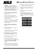
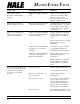
Fastener Torque Specifications: Unless
otherwise specified use the following
torque values for fasteners used on MIV
valves.
ELBATEUQROT
EZISWERCS)%01-+(EULAV
04-4#)m-N6.0(ni-bl5
23-6#)m-N1.1(ni-bl01
42-01#)m-N5.2(ni-bl22
6M)m-N6.3(ni-bl23
)M-VIM(61-8/3)m-N02(tf-bl51
)E-VIM(61-8/3)m-N43(tf-bl52
41-61/7)m-N45(tf-bl04
NOINURTREWOL)m-N361(tf-bl021
Table 1. Fastener Torque Values