1/1/98 MASTER INTAKE VALVE DESCRIPTION, INSTALLATION AND OPERATION MANUAL All Hale products are quality components: ruggedly designed, accurately machined, precision inspected, carefully assembled and thoroughly tested. In order to maintain the high quality of your unit, and to keep it in a ready condition, it is important to follow the instructions on care and operation. Proper use and good preventive maintenance will lengthen the life of your unit.
MASTER INTAKE VALVE Table of Contents SECTION 1 2 3 4 5 6 7 8 9 PAGE SAFETY .................................................................................................................... 1 GENERAL DESCRIPTION ........................................................................................ 3 INSTALLATION ......................................................................................................... 6 OPERATION .........................................................................
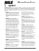
MASTER INTAKE VALVE 1 SAFETY IMPORTANT NOTICE: Before attempting installation or operation of the Hale MIV read and follow all safety precautions listed below. The warnings and cautions listed are necessary for the safe installation and operation of the Hale MIV. When developing departmental apparatus operating procedures make sure the warnings and cautions are incorporated as written. 1. WARNING: The outlet of the relief valve can flow large volumes of water under pressure.
MASTER INTAKE VALVE Care must be taken when removing gearmotor cover. 13. WARNING: When initially charging large diameter hose excessive air will be present in the hose. This air must be bled off while the hose is charging and prior to opening the Hale MIV to prevent receiving pump cavitation and possible loss of prime. 14. WARNING: When the electric motor driven valve is operated the manual override handwheel will turn. Keep hands, feet or loose clothing away from the handwheel to prevent entanglement. 15.
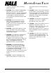
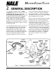
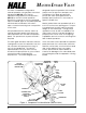
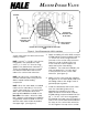
MASTER INTAKE VALVE 2 GENERAL DESCRIPTION The Hale Master Intake Valve is a NFPA compliant large diameter intake valve that is mounted in the pump suction tube behind the pump operator panel. The valve is a butterfly type valve that is available either in manual or electric operation. Safety features on the valve include an integral relief valve and air bleeder valve tap that vent to the atmosphere. The valve assembly, less relief valve, is factory tested to 600 PSI (41 Bar).
MASTER INTAKE VALVE The valve is available configured for manual operation using a panel mounted handwheel (MIV-M) or for electric operation using a panel mounted switch (MIV-E) for remote control operation. Whether the manual or electric operated valve is installed, lights on the panel placard will illuminate to indicate if the valve is open, closed or traversing from one position to the other. designed to permit operation with minimal torque even at high flows and pressures.
MASTER INTAKE VALVE The surface between the mounting flanges and Hale MIV valve body are sealed using reliable o-ring seals in grooves machined in the Hale MIV body. Design of the relief valve permits the discharge to be piped behind the operator panel for increased operator and/or bystander safety.
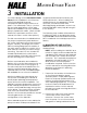
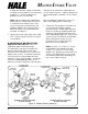
MASTER INTAKE VALVE 3 INSTALLATION The unique design of the Hale Master Intake Valve permits installation in the fire pump suction tube behind the pump compartment panel using a minimum of space. The valve body is only 3-3/8 inches (86 mm) wide and various suction tube options are available to fit most standard pump compartment widths. (Refer to Hale Bulletin 596, reprinted in section 9 of this manual, for various suction tube options.
MASTER INTAKE VALVE GEARBOX RELIEF VALVE STUD OR CAP SCREW NOT USED IN THIS HOLE STUD OR CAP SCREW NOT USED IN THIS HOLE STUDS PLACED IN THESE HOLES LOOKING INTO SUCTION TUBE FROM OUTSIDE PUMP PANEL Figure 3. Stud Placement for MIV Installation suction tube extension and suction tube mating surfaces.
MASTER INTAKE VALVE threads are started. Apply Loctite #242 or equal to the threads on the studs and install the 7/16-14 UNC grade 5 zinc plated steel nuts on the studs. Hale MIV-E on the bottom opening of this suction tube extension. Ordinary flanges will not provide proper clearance for the valve disc. NOTE: When installing the Hale Master Intake Valve 8 suction tube cap screws, 2 studs and 2 nuts will be used.
MASTER INTAKE VALVE NOTE: All cap screws, studs and nuts must be locked in place using Loctite #242 or equal thread sealing compound. NOTE: When the valve body is installed make sure the valve disc is next to the suction tube extension. The relief valve, drain valve, air bleeder valve and priming valve must be located on the inlet side of the valve.
MASTER INTAKE VALVE b. The relief valve mounting pad on the Hale MIV valve body has 2-½ inch NPT female threads, install a 2-½ inch NPT threaded pipe nipple into the mounting pad. c. Screw a 2-½ inch NPT Hale type 115 4-3/8 inch bolt circle flange (Hale P/N 115-0070-00-0) onto the pipe nipple. d.
MASTER INTAKE VALVE NPT threaded hole in the bushing. 4. Install the remaining ¼ inch NPT X 3/8 inch tube compression fitting into inlet of the air bleeder valve body. Hold the valve with a wrench. CAUTION: To prevent damage to the valve body hold the hex outlet on the valve with a wrench while tightening elbow. 5. Install the ¼ inch NPT X 3/8 inch tube compression elbow into the hex outlet of the air bleeder valve.
MASTER INTAKE VALVE 9. Install and tighten the retaining nut on the valve body making sure the valve remains in the correct orientation. 10. Install the valve handle and tighten setscrew with allen wrench. 2.25 IN. (57 MM) 3.25 IN. (83 MM) 1.63 IN. (41 MM) 0.75 IN. (19 MM) 0.25 IN. (6 MM) RADIUS TYPICAL 3.66 IN. (93 MM) 2.38 IN. (60 MM) 2.75 IN. (70 MM) 0.53 IN. (13 MM) 0.25 IN. (6 MM) 2.75 IN. (70 MM) 0.28 IN. (7 MM) DIAMETER HOLE (4 PLACES) A. 1.00 IN. (25 MM) DIAMETER HOLE 0.28 IN.
MASTER INTAKE VALVE 11. Determine location on the operator panel for the air bleeder valve and cut holes in the panel according to the dimensions shown in figure 7D. 12. Install panel placard with valve attached and secure in place using the ¼-20 UNC X 1 inch long cap screws and ¼-20 UNC nuts provided. WARNING: Use tubing rated at the maximum discharge pressure of the fire pump, 500 PSI (34 BAR) minimum. additional priming pump is installed or a three way valve is installed to control priming. G.
MASTER INTAKE VALVE 2. Connect the wiring harness from the panel placard to the wiring harness from the gearbox adapter. The Packard WeatherPack end connectors are keyed and will only assemble one way. 3. Connect +12 VDC power to the RED pigtail provided using 14 AWG type SXL or GXL (SAE J1128) wire. Make sure the power supply is capable of providing 12 VDC power at 10 AMPS. Connect the end of the BLACK wire to a ground point on the chassis frame.
MASTER INTAKE VALVE apparatus to normal ready condition. 4. Open water supply valve and air bleed valve. Fill suction tube until water flows from air bleed. Close air bleed. 5. Pressurize to desired set pressure in accordance with the above warnings. Observe whether relief valve opens or remains closed at the desired pressure. 6. Using a 3/16 inch allen wrench loosen, BUT DO NOT REMOVE, the screw that locks the pressure adjustment cap screw. 7.
MASTER INTAKE VALVE head screws. Do not remove gearmotor -the drive pin could drop out. Rotate gearmotor so circuit breaker is located toward top. Apply Loctite #242 or equal to threads of #6-32 socket head screws reinstall and tighten. 9. Be sure wiring connections are properly and firmly attached. Slide strain relief in cover cutout and slide cover over gearmotor and adapter lining up holes. Apply Loctite #242 or equal to threads of #6-32 screws reinstall and tighten. 10.
MASTER INTAKE VALVE 4 OPERATION WARNING: Per NFPA1962 requirements, large diameter hose used to supply a pumper from a hydrant or another pumper shall be connected to the pumper(s) and hydrant with a slight downward bend to avoid kinking when the water is turned on. WARNING: Per NFPA1962 requirements, large diameter hose marked “SUPPLY HOSE” 3-½ to 5 inches (89 to 127 mm) diameter shall not be used at operating pressures exceeding 185 PSI (13 BAR).
MASTER INTAKE VALVE 2. To open valve, push toggle switch (figure 8 A) to the OPEN position and hold until the green OPEN indicator lights. If apparatus configuration permits, observe the manual override handwheel on the operator panel to make sure the valve is turning. Release the switch. 3. To close valve, push toggle switch to the CLOSED position and hold until the red CLOSED indicator lights.
MASTER INTAKE VALVE 4.00 IN. (102 MM) 3.50 IN. (89 MM) 2.00 IN. (51 MM) 1.13 IN. (29 MM) 3.10 IN. (79 MM) GREEN LAMP 4.25 IN. (108 MM) 4.00 IN. (102 MM) AMBER LAMP RED LAMP TOGGLE SWITCH A. 3.25 IN. (83 MM) DIAMETER HANDWHEEL B. ELECTRIC OPERATED VALVE ELECTRIC OPERATED VALVE MANUAL OVERRIDE HANDWHEEL 4.50 IN. (114 MM) 1.50 IN. (38 MM) 2.63 IN. (67 MM) 1.31 IN. (33 MM) 3.13 IN. (80 MM) RED LAMP 5.37 IN. (136 MM) 2.09 IN. (53 MM) AMBER LAMP 3.00 IN. (76 MM) GREEN LAMP 5.00 IN.
MASTER INTAKE VALVE 5 MAINTENANCE After each use: 1. Visually inspect the valve to make sure there is no debris caught between the valve body and valve disc. 2. If the system was operated with salt water, foam or contaminated water, flush valve and pump with fresh water in accordance with departmental procedures. 3. Cycle the valve to make sure the valve still operates smoothly. Apply Sunoco Ultra Prestige 2EP grease or equal to valve disc edges and to valve bore as necessary.
MASTER INTAKE VALVE 12. Clean and inspect all components for damage and/or excessive wear. Replace those components beyond repair. 19. If switches need to be replaced refer to instructions on MICRO SWITCH REPLACEMENT. 20. Install a new gasket to gearbox adapter. 13. Install a new o-ring into the groove on the valve disc stem. Apply a light coat of Sunoco Ultra Prestige 2EP grease or equal to the stem, o-ring and pivoting surfaces of the new disc. 14.
MASTER INTAKE VALVE MICRO SWITCH REPLACEMENT: If inspection or if troubleshooting indicates that replacement is necessary order switch replacement kit (Hale P/N 200-1210-50-0) for MIV-M or switch replacement kit (Hale P/N 200-1210-52-0) for MIV-E and proceed as follows: 1. To avoid damage to switch rollers, manually rotate the valve to the half open position. Approximately 5 turns from either the fully open or fully closed position.
MASTER INTAKE VALVE WIRING HARNESS MICRO SWITCH (4 REQUIRED MIV-E) (2 REQUIRED MIV-M) GEARBOX ADAPTER GASKET SHAFT THRUST WASHER SWITCH PLATE 3 /8 -16 X 2-½ CAP SCREW #10-24 X ½ SCREW (MIV-E) #4-40 X 1 SCREW (MIV-M) #4-40 X ½ SCREW SPACER (MIV-E) MIV-E GEARMOTOR/ GEARBOX ASSEMBLY SHAFT MIV-M GEARBOX Figure 9. Micro Switch Replacement tap in the gearbox adapter. Tighten fitting in ¾ inch NPT tap. Do not tighten strain relief nut.
MASTER INTAKE VALVE 26. Slightly loosen the two 7/16-14 x 1 inch long counterbore screws that hold the gearbox adapter to the valve body. PINCH MICRO SWITCHES WHERE INDICATED BY ARROWS WHILE TIGHTENING SCREWS 27. Manually turn back gearbox handwheel a small amount until gearbox and gearbox adapter are free to move. Find the mid position of this free play and tighten the two mounting screws. 22. Apply a light coat of Sunoco Ultra Prestige 2EP grease or equal to the valve bore and the disc edges. 28.
MASTER INTAKE VALVE ➪ DISCHARGE SIDE OF VALVE B=A± ± 1/16 A ➪ B ➩ ➩ EXAMPLE: A MEASURES 5/8 INCH B MUST MEASURE 9/16 TO 11/16 INCH Figure11. Valve Disc Position Measurement directions. Check lamp operation and disc stop position, if necessary back out screw a small amount until lamp and stop sequence properly. b) Replace rubber plug. b. Electric valves (MIV-E) a) Operate the valve open then closed. See that motor stops, the red lamp is lit and valve disc is in the closed position.
MASTER INTAKE VALVE WARNING: The relief valve spring is under pressure and can cause a projectile hazard. When disassembling the relief valve, back relief valve adjustment screw out to lowest setting to relieve pressure on spring before removing relief valve housing screws. 4. Using a 3/16 inch Allen wrench remove the pressure adjustment cap screw locking screw. 5. Using a 7/8 inch open end wrench, remove the pressure adjustment cap screw to relieve pressure on the adjustment spring. 6.
MASTER INTAKE VALVE 6 TROUBLESHOOTING SYMPTOM PROBABLE CAUSE REMEDY Valve is difficult to open or close Little or no grease on valve disc (New valves may require more lubrication until valve disc and bore wear in) Lubricate valve: Remove strainer from suction connection. Manually operate valve to open position and coat valve bore and disc edges with Sunoco Ultra Prestige 2EP grease or equal. Valve left closed for extended periods Periodically operate valve to ensure proper operation.
MASTER INTAKE VALVE SYMPTOM PROBABLE CAUSE REMEDY Valve is difficult to operate (Sticks, Jams or Binds. Sometimes intermittently) (Cont’d) Forked end of valve shaft digging into gearbox adapter bore. Check valve shaft forked end. edges of slot should not be sharp, remove sharp edges with file or emery cloth. Remove chips or burrs from gearbox adapter bore. MIV-E Valve has water in gearbox adapter housing Water seeps between indicator cover and segment gear.
MASTER INTAKE VALVE SYMPTOM PROBABLE CAUSE REMEDY Amber lamp stays lit; does not change to green or red when valve is either fully open or closed (on MIV-E valve turning the manual override handwheel a slight amount changes light) MIV-M mechanical stop(s) improperly adjusted Adjust mechanical stop(s) for proper operation. MIV-E manual override handwheel only needs to be turned a slight amount and light changes. Improperly installed micro switch(es).
MASTER INTAKE VALVE MASTER INTAKE VALVE MAXIMUM OPERATING TORQUE TO OPEN TO CLOSE 100 lb-in (11 N-m) 100 lb-in (11 N-m) RUNNING 25 lb-in (3 N-m) Table 2. Maximum Operating Torque NOTE: On MIV-M valves the maximum force at the knob on the handwheel is 46 lb (205 N) to open or close and 11 lb (49 N) running. TESTING MIV-E VALVES FOR PROPER OPERATION The following is a test to determine if the MIV-E valve is operating correctly electrically. 1.
MASTER INTAKE VALVE NOTE: Limit switches are shown with the actuating plungers depressed and the valve in a partially open position. The amber indicator is lighted with the switches in this position. BROWN-18 Figure 12.
MASTER INTAKE VALVE NOTE: Limit switches are shown with the actuating plungers depressed and the valve in a partially open position. The amber indicator is lighted with the switches in this position. Figure 13.
44 38 41 39 36 42 40 37 35 29 14 61 62 34 63 62 34 35 13 32 33 31 33 30 33 26 54 10 53 23 14 24 8 16 9 33 8 30 33 31 33 35 64 12 9 11 34 27 5 25 46 60 3 23 24 4 7 2 46 15 1 20 21 59 MANUAL VALVE ACTUATOR ASSEMBLY 49 48 51 50 58 22 7 6 18 19 56 SUCTION TUBE 22 17 57 PARTS LIST 55 43 53 28 21 48 47 52 7 27 SUCTION EXTENSION AIR BLEEDER VALVE ASSEMBLY MASTER INTAKE VALVE 33
MASTER INTAKE VALVE PARTS LIST Item Part Number Qty 538-1560-00-0 538-1560-20-0 538-1560-25-0 538-1560-27-0 1 2 3 4 5 6 7 8 9 10 11 12 13 14 15 16 17 18 19 20 21 22 23 24 25 34 038-1740-01-0 505-0230-00-0 040-1159-00-0 007-3250-00-0 018-1810-22-0 041-0520-00-0 040-9160-00-0 037-2110-00-0 1 1 1 1 2 1 2 1 037-1940-01-0 1 037-2110-01-0 1 037-1941-01-0 1 200-1210-00-0 200-1210-00-0 018-0404-45-0 018-0410-45-0 005-1210-00-0 018-1004-27-0 097-1950-00-0 2 4 4 4 1 2 1 531-0150-00-0 531-0160-00-0 018
MASTER INTAKE VALVE PARTS LIST (Cont’d) Item Part Number Qty 26 101-1480-02-0 1 27 513-0270-52-0 1 513-0270-53-0 1 36 37 38 200-1220-00-0 200-1220-01-0 200-0540-01-0 200-0540-04-0 200-0540-11-0 200-0540-02-0 018-1205-44-0 018-1205-44-0 110-1200-02-0 110-1200-02-0 007-3330-00-0 218-0608-08-0 200-1250-50-0 1 1 1 1 1 3 8 4 8 4 1 4 1 39 40 064-6350-00-0 018-0604-08-0 1 4 41 42 43 44 45 46 47 48 49 50 51 52 53 54 55 56 57 58 59 60 61 62 63 200-1240-00-0 048-1080-01-0 044-1480-00-0 018-0604-45-0
MASTER INTAKE VALVE VALVE DISC REPLACEMENT KIT 546-1620-00-0 1 VALVE DISC REPLACEMENT KIT Consists of the following items: 505-0230-00-0 1 DISC 040-1159-00-0 1 QUAD-RING 040-9160-00-0 2 TRUNNION SEAL 046-6650-00-0 1 GEARBOX ADAPTER GASKET 142-0110-00-0 2 SQUARE SEAL RING GEARMOTOR/GEARBOX REPLACEMENT ASSEMBLY 531-0150-50-0 1 GEARMOTOR/GEARBOX REPLACEMENT ASSEMBLY Consists of the following items: 531-0150-00-0 1 GEARBOX 007-3330-00-0 1 GEARMOTOR ADAPTER 218-0608-08-0 4 SCREW, M6 x 16mm LG. SOC. HD.
MASTER INTAKE VALVE 8 WARRANTY LIMITED WARRANTY EXPRESS WARRANTY. Hale Products Inc. (“Hale”) hereby warrants to the original buyer that products manufactured by it are free of defects in material and workmanship for two (2) years or 2000 hours usage, whichever shall first occur. The “Warranty Period” commences on the date the Product is first placed in service. LIMITATIONS. HALE’S obligation is expressly conditioned on the Product being.
MASTER INTAKE VALVE 9 38 INSTALLATION DIMENSIONS
MASTER INTAKE VALVE Suction Tube Extension Options 39
MASTER INTAKE VALVE Hale MIV-E mounting dimensions 40
MASTER INTAKE VALVE Hale MIV-M mounting dimensions 41
MASTER INTAKE VALVE Hale MIV-E Bottom Suction Mounting Dimensions (Right Side Front, Left Side Rear Operator) 42
MASTER INTAKE VALVE Hale MIV-E Bottom Suction Mounting Dimensions (Right Side Rear, Left Side Front Operator) 43