
User Manual


❑ Illustrated Parts Breakdown
164
FoamLogix 3.3 / 5.0 / 6.5 Installer / Operations Manual
p/n: 029-0021-68-0
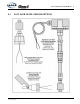
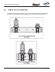
8.6 FLOW SENSORS
Each Hale foam system requires a flow sensor to operate. Pipe size must be selected based on
the minimum and maximum water flow in the foam capable discharge. Following is a list of pipe
size and rated flow ranges along with flow sensor saddle clamp part numbers. In all instances a
weld fitting may be substituted for the saddle clamp.
Pipe Size
Flow Range
GPM LPM
1½” (38mm) 10 - 330 38 - 1,249
2” (50mm) 20 - 550 76 - 2,082
2½” (64mm) 30 - 800 114 - 3,028
3” (76mm) 50 - 1,250 189 - 4,732
4” (102mm) 75 - 1,800 284 - 6,814
SCV or DCV 30 - 750 114 - 2,839