
User Manual


103
FoamLogix 3.3 / 5.0 / 6.5 Installer / Operations Manual
p/n: 029-0021-68-0
Start-Up Check List ❑
Foam Pump
Refer to the following heading for overview drawings of typical plumbing
arrangements:
● See Section 3.5 “System Plumbing Diagrams” on page 77.
● See Section 3.1 “Foam Pump and Motor Assembly” on page 48.
❑ Foam pump and motor assembly mounted in horizontal position with
base plate down.
❑ Foam pump and motor assembly properly secured using proper mount-
ing hardware.
❑ Foam pump suction and discharge hoses connected to proper ports.
❑ Foam pump suction and discharge hose fittings tight.
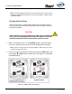
Optional ADT
● See Section “ADT Option Air Connections” on page 73.
❑ Panel placard mounted on the operator panel.
❑ Air hose connected and all connections are tight.
❑ Selector switch is in the TANK “A” position
❑ Bypass valve handle is in the INJECT position.