
User Manual


❑ Start-up Check List
102
FoamLogix 3.3 / 5.0 / 6.5 Installer / Operations Manual
p/n: 029-0021-68-0
❑ If ADT, MST or MDT II are used, check electrical cable connects.
❑ If the Remote Activation Switch is used, check electrical cable connec-
tions from the On/OFF switch.
Liquid
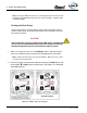
Refer to the following heading for overview drawings of typical plumbing
arrangements:
● See Section 3.5 “System Plumbing Diagrams” on page 77.
● See Section “Plumbing Installation” on page 59.
❑ Flow sensor mounted with flow arrow in the correct direction for water
flow.
❑ Check valves are properly mounted in water and foam concentrate lines.
❑ Strainer mounted for proper concentrate flow direction in foam tank to
pump hose.
❑ Foam tank to foam pump valve is in place and open.
❑ Check valve/injector fitting lines are the proper size and connections are
tight.
❑ Bypass valve is properly mounted and oriented for direction of concen-
trate flow.
❑ Foam concentrate gravity feeds to foam pump from foam concentrate
tank.
❑ All hoses free of kinks and sharp bends.
❑ No sharp bends that can trap air exist in system.
❑ Flush water connections correct and tight.
MST properly positioned with respect to the Foam Tank, or MDT II to
Tank “A”
❑ Discharge piping hydro tested in accordance with NFPA/UL
requirements.
❑ Bypass valve handle is in the INJECT position.