
User Manual


101
FoamLogix 3.3 / 5.0 / 6.5 Installer / Operations Manual
p/n: 029-0021-68-0
Start-Up Check List ❑
3.7 START UP CHECK LIST
Before energizing the apparatus and the Hale FoamLogix system for the
first time make sure the following items are checked:
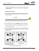
Electrical
Refer to the following for an overview of electrical connections:
● Figure 3-33: “Dual Tank Electrical Harness Overview” on page 88
● Figure 3-34: “Control/Display Unit Mounting Dimensions” on page 89
● For cable harness overviews, see Section “ 9 Plate Drawings,” beginning on
page 170.
● Figure 3-35: “Distribution Box Connections” on page 90
❑ Tank LOW level sensor wires extended, if necessary, and connected to
main cable harness (C10, C11).
❑ Tank LOW level sensor wires sealed against moisture with silicone seal-
ant provided.
❑ Tank LOW level sensor(s) function properly.
❑ For single tank operation, if the Hale MST is not used, check that the
tank select jumper plug is installed at connector C8.
❑ Control cable connection at distribution box is correct and tight.
❑ Flow sensor cable properly connected to main cable harness (C3).
❑ All cables and wires are secured and protected from damage during
operation.
❑ Control and flow sensor cables properly folded and secured; radio anten-
nas, power lines and equipment away from cables.
❑ Foam pump and motor assembly properly grounded using flat ground
strap.
❑ Correct voltage provided. Direct current, negative (–) ground.
❑ Adequate current, 60 AMPS minimum, available. Main power direct to
battery, battery switch or solenoid without primer or other accessories
tied in.
❑ Primary electrical and ground connections tight and protected from cor-
rosion with silicone sealant.
❑ Splices in wires sealed from moisture using adhesive filled heat shrink
tubing.