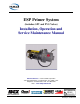
ESP Primer System (Includes: SPV and PVG Valves) Installation, Operation and Service Maintenance Manual Hale Products Inc. ◆ A Unit of IDEX Corporation 700 Spring Mill Avenue ◆ Conshohocken, PA 19428 U.S.A. Telephone: 610-825-6300 ◆ FAX: 610-825-6440 Web......www.haleproducts.
NOTICE ! Hale Products, Inc. cannot assume responsibility for product failure resulting from improper maintenance or operation. Hale is responsible only to the limits stated in the product warranty. Product specifications contained in this manual are subject to change without notice. All Hale products are quality components -- ruggedly designed, accurately machined, precision inspected, carefully assembled and thoroughly tested.
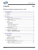
Table of C ont ents ❑ Contents Page ESP Primer Installation, Operation and Service Guide 1 2 Safety Precautions................................................................................................... 7 1.1 Definitions........................................................................................................................... 7 1.2 Guidelines ...........................................................................................................................
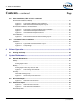
❑ Ta ble of Contents Contents - continued 3.2 Page Valve Installation, SPV or PVG - continued SPV Retrofit Installation, Midship ..................................................................................................... 22 Figure 3-4: Figure 3-5: Typical SPV / Midship Pump Installation............................................................. 22 SPV Retrofit Panel Placard Spacer Layout ......................................................... 23 SPV Retrofit Installation, Universal Mount.
Table of C ont ents ❑ Contents - continued 5.4 Page Lubricant Specifications.................................................................................................. 45 Grease, for O-ring Seals ................................................................................................................... 45 Loctite Sealant .................................................................................................................................. 45 Recommended Cleaners ................
❑ Ta ble of Contents Contents - continued Page Notes _______________________________________________________________________ _______________________________________________________________________ _______________________________________________________________________ _______________________________________________________________________ _______________________________________________________________________ _______________________________________________________________________ ________________________
Safe ty 1 ❑ Safety Precautions IMPORTANT ! THE HALE ESP PRIMER SYSTEM, WHICH INCLUDES THE SEMI-AUTOMATIC PRIMING VALVE (SPV) OR THE PVG PRIMER VALVE, IS DESIGNED FOR OPTIMUM SAFETY OF ITS OPERATORS. FOR ADDED PROTECTION, PLEASE FOLLOW THE SAFETY GUIDELINES LISTED IN THIS SECTION. ADHERE TO ALL WARNING, DANGER, CAUTION AND IMPORTANT NOTES FOUND WITHIN THIS MANUAL.
❑ Sa fet y NOTICE ! NOTICE - Practices which could result in damage to the apparatus or other property. 1.2 GUIDELINES NOTICE ! THE PROCEDURES IN THIS MANUAL ARE GENERAL OPERATING PROCEDURES. THEY DO NOT REPLACE THE PROCEDURES, POLICIES OR GUIDELINES ESTABLISHED BY THE AUTHORITY HAVING JURISDICTION, NOR DO THEY REPLACE THE RECOMMENDATIONS AND PROCEDURES PROVIDED IN THE APPARATUS MANUFACTURER'S MANUAL.
Safe ty ❑ CAUTION - continued ! BE SURE TO WEAR SAFETY GLASSES WHEN REMOVING AND/OR INSTALLING FORCE (PRESS) FITTED PARTS. FAILURE TO COMPLY MAY RESULT IN SERIOUS INJURY. ❑ Parts under spring tension can become projectiles and cause serious injury. When removing or installing these parts make sure they are restrained and spring tension is released slowly. ❑ Disconnect or turn OFF the master battery switch prior to servicing the Hale SPV or PVG electrical components.
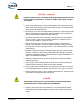
❑ Sa fet y Holding the primer ON for two (2) or three (3) seconds after a prime from draft will clean out residue in the primer. ❑ DO NOT run the primer over forty-five (45) seconds. If prime is not achieved within 45 seconds, stop and look for causes (air leaks or blocked suction hoses). ❑ Always use caution when handling or disposing of propylene glycol. ❑ DO NOT USE ETHYLENE GLYCOL. ❑ DO NOT allow coolant to discharge to the ground.
❑ Introduction 2 Introduction 2.1 ESP PRIMER PUMP Hale recommends and uses Rotary Vane Positive Displacement pumps (ESP) for priming. Priming pumps are used to evacuate air in the suction hose and pump. (See Figure 2-1: “Rotary Vane ESP Priming Pump.”) Figure 2-1: Rotary Vane ESP Priming Pump The Hale ESP series priming pump is an environmentally friendly primer that does not require a separate lubricant reservoir. The vanes and pump body are self-lubricating for maintenance free operation.
❑ Introduction 2.2 SPV PRIMING VALVE The Hale Semi-Automatic Priming Valve (SPV) simplifies the priming operation of your pump allowing for a faster priming time and longer primer life . The SPV is a diaphragm-operated valve that opens using the vacuum generated by the priming pump. Easily activated by a push button control, the SPV starts the primer motor creating a vacuum. The vacuum acts on the diaphragm in the valve causing the port to open allowing vacuum. (See Figure 2-2: “SPV Overview.
❑ Introduction The short length of hose also allows for a faster priming time and longer primer life by reducing the volume that must evacuated. The priming pump motor is push-button operated, located on the pump operator panel of the apparatus. There are NO hose connections at the pump operator panel thus saving valuable space. Depressing and holding the PRIME push button energizes the priming pump motor creating a vacuum in the 3/4” (19 mm) ID hose.
❑ Introduction Primer Mounted on Midship Pump This option mounts the Hale SPV to the priming flange connection on a “new” midship pump body with the priming pump mounted to the pump gearbox. When this option is ordered, the vacuum hose is connected from the Hale SPV to the priming pump. Components included with this option and shipped with the midship pump are the push button switch, panel placard and Installation Manual.
Introduction ❑ Figure 2-4: Typical ESP Lubricated System The Hale ESP Priming System can be converted to a “lubricated system” by installing “separate” lubricant and discharge tanks and using a Propylene Glycol / water mixture as the lubricant. (See Figure 2-4: “Typical ESP Lubricated System.”) Propylene Glycol is a less toxic and more environmentally-friendly coolant and is recommended over Ethylene Glycol based antifreeze.
❑ Introduction Coolant Water Freezing Point F° (C°) 50% 50% -26 (-32) 60% 40% -54 (-48) 66% 34% -76 (-60) Chart 2-5: Typical Freeze-Up Protection IMPORTANT! IF THERE IS PRIMER LUBRICANT IN THE RESERVOIR, IT IS RECOMMENDED TO OPERATE LUBRICATED PRIMING SYSTEMS WEEKLY TO CYCLE THE FRESH LUBRICANT THROUGH THE PRIMER. HOLDING THE PRIMER ON FOR TWO (2) OR THREE (3) SECONDS AFTER A PRIME FROM DRAFT WILL CLEAN OUT RESIDUE IN THE PRIMER.
❑ Insta llation 3 System Installation ESP Primer Systems are available mounted to Midship pump gearboxes or to the pump body on new orders. 3.1 PRIMER PUMP For the Hale 12 volt ESP Primer System installation instructions see drawing “12 Volt ESP System” on page 54. For the 24 volt ESP Primer System installation instructions see drawing “24 Volt ESP System” on page 54. Notes: The 12 and 24 volt drawings offer two sheets, one for mechanical installation and one for electrical.
❑ Insta llation Attach the ground strap from the truck chassis to the priming pump terminal stud to ensure a ground for the motor. See appropriate drawing, sheet 2. The ground strap is appropriately sized for a 12 or 24 volt DC, 300 or 150 amp load. ❑ To prevent damage to the solenoid plastic housing, when installing or removing wire leads, DO NOT apply side loads to the nuts. (See Figure 3-1: “Solenoid Connector Arrangement.
❑ Insta llation NOTICE ! DO NOT RUN THE PRIMER OVER FORTY-FIVE (45) SECONDS. IF PRIME IS NOT ACHIEVED WITHIN 45 SECONDS, STOP AND LOOK FOR CAUSES (AIR LEAKS OR BLOCKED SUCTION HOSES). Optional Bracket Installation A mounting bracket is available to install the Hale ESP primer pump to some competitive pumps. Contact Hale Customer Service for additional information. ESP System Plate Drawings Hale ESP-12 Priming Pump, Mechanical Installation, Sheet 1 of 2 ...................................................
❑ Insta llation Figure 3-2: Typical Hale SPV Typical System Layout SPV Placard and Pushbutton WARNING ! DISCONNECT OR TURN OFF THE MASTER BATTERY SWITCH PRIOR TO SERVICING THE HALE SPV ELECTRICAL COMPONENTS.
❑ Insta llation WARNING - continued ! MAKE SURE THERE IS NO POWER AT THE PRIMER SOLENOID BEFORE STARTING SERVICE PROCEDURES. ALSO SEE SECTION 1 “SAFETY PRECAUTIONS” ON PAGE 7. 1. Carefully locate the position of the pushbutton switch on the apparatus operator control panel. (See Figure 3-3: “SPV Pushbutton Placard Overview.”) Figure 3-3: SPV Pushbutton Placard Overview ESP Primer System Instruction Guide p/n: 029-0810-01-0 2. Drill or punch a 0.64” (16 mm) diameter hole in the panel. 3.
❑ Insta llation 8. ❑ Install minimum 14 AWG type SXL or GXL wire (SAE J1128) from one switch terminal to the priming pump solenoid connection. Secure the ring terminal to the push button switch using the screws provided. (See Figure 3-3: “SPV Pushbutton Placard Overview,” on page 21.) ❑ Install minimum 14 AWG type SXL or GXL wire (SAE J1128) from the other switch terminal to the positive battery power. Secure the ring terminal to the push button switch using the screws provided with the switch.
❑ Insta llation WARNING ! DISCONNECT OR TURN OFF THE MASTER BATTERY SWITCH PRIOR TO SERVICING THE HALE SPV ELECTRICAL COMPONENTS. MAKE SURE THERE IS NO POWER AT THE PRIMER SOLENOID BEFORE STARTING SERVICE PROCEDURES. 2. Drain all water from pump body. 3. Open the pump operator panel to gain access to the existing Hale PVG. 4. Disconnect the electrical leads and vacuum hoses to the Hale PVG. 5. If the Hale PVG is mounted at the operator panel, remove the Hale PVG and placard. 6.
❑ Insta llation 7. Connect electrical leads to the pushbutton contacts. 8. Locate the priming valve flange on the midship pump. (See Figure 3-4: “Typical SPV / Midship Pump Installation,” on page 22.) The priming valve flange is located next to the gearbox on the midship pump. 9. Remove the 7/16”-14 screws that hold the priming flange, hose and fittings on the midship pump body. Remove the flange assembly from the pump body. 10. Remove the strainer and seal ring from the pump body.
❑ Insta llation SPV Retrofit Installation, Universal Mount When installing the Hale SPV assembly with a universal mounting adapter use the following procedures. (See Figure 3-6: “Typical SPV / Universal Adapter Pump Installation.”) Figure 3-6: Typical SPV / Universal Adapter Pump Installation 1. Place the apparatus out of service in accordance with departmental procedures. CAUTION ! MAKE SURE THE HALE SPV IS LOCATED HIGHER THAN THE PUMP BODY ALLOWING WATER TO DRAIN FROM THE VACUUM HOSE. 2.
❑ Insta llation 3. Drill two 29/64” (12 mm) holes 2-1/2” (64 mm) apart to attach the universal mounting adapter to a secure point on the apparatus. (See Figure 37: “Universal Mount Adapter Dimensions.”) 4. Select the proper mounting adapter orientation and using the 7/16”14 x 1.0” screws attach the universal mounting adapter to the apparatus. (See Figure 3-8: “Universal Mount Adapter Positions.”) 5.
Insta llation 7. ❑ Apply a light coating of thread locking compound (Loctite #290 or equal) to the exposed stud threads. Secure the Hale SPV valve in place on the universal mounting adapter using 7/16-14 nuts. WARNING ! USE ONLY PIPE, HOSE, AND FITTINGS FROM THE PRIMING PUMP VACUUM CONNECTION TO THE HALE SPV VACUUM CONNECTION RATED FOR 29 IN. (737 MM) HG. VACUUM. 8. Attach 3/4” (19 mm) ID vacuum hose from the hose connection on the Hale SPV to the priming pump connection.
❑ Insta llation 3. Drill or punch one 1.032” (26 mm) and two 0.266” (7 mm) diameter holes in the panel. (See Figure 3-9: “PVG Panel Placard and Valve Plumbing Layout.”) Figure 3-9: PVG Panel Placard and Valve Plumbing Layout 28 4. Install the PVG panel placard and valve body to the operator’s panel. (See Figure 3-9: “PVG Panel Placard and Valve Plumbing Layout.”) 5. Secure the assembly with two (2) 1/4”-20 screws. Apply a drop of Loctite #246 to each screw. 6.
❑ Insta llation 10. Connect the PVG electrical connector to proper system electrical source. For specification, see Section Drawing Package, Hale plate drawing “PVG Priming Valve” on page 54. 3.3 LUBRICATED PRIMER INSTALLATION Also see Figure 3-10: “Typical ESP Lubricated Primer Layout” on page 30. To convert a Hale ESP Non-Lubricating Priming System to a Lubricated Priming System, the following parts are required for optimum performance and to conform to most regional environmental regulations.
❑ Insta llation WARNINGS - continued ! ❑ ALWAYS USE CAUTION WHEN HANDLING OR DISPOSING OF PROPYLENE GLYCOL. ❑ DO NOT USE ETHYLENE GLYCOL. The tank should be a translucent, polypropylene tank to allow visual inspection of the lubricant level. Order Hale p/n: 108-0012-00-0 (4 quart / 3.8 liter capacity), which includes the 1/8” NPT x 5/16” (8 mm) tube fitting with a #60 vent hole. (See Figure 3-10: “Typical ESP Lubricated Primer Layout.”) Figure 3-10: Typical ESP Lubricated Primer Layout 1.
❑ Insta llation 2. Remove the 1/8” NPT pipe plug in the top of the primer pump and install one 1/8” NPT x 5/16” (8 mm) tube fitting. (See Figure 3-11: “Pump Fittings.”) Use appropriate thread sealant.
❑ Insta llation WARNING - continued ! ALWAYS FOLLOW THE MANUFACTURER’S RECOMMENDED INSTRUCTIONS ON THE LABEL AFIXED TO THE CONTAINER. Notes: ❑ DO NOT use water only in the lubricant tank in FREEZING climates. ❑ The propylene glycol must be the type that includes corrosion inhibitors. An example would be propylene glycol antifreeze recommended for the RV or Marine type cooling systems. 8.
Ope ration 4 ❑ Primer Operation WARNING ! THE PROCEDURES IN THIS SECTION ARE GENERAL OPERATING PROCEDURES. NOT ALL PROCEDURES IN THIS SECTION MAY APPLY TO YOUR SPECIFIC OPERATIONAL REQUIREMENTS. THESE PROCEDURES DO NOT REPLACE THE PROCEDURES, POLICIES OR GUIDELINES ESTABLISHED BY THE AUTHORITY HAVING JURISDICTION, NOR DO THEY REPLACE THE RECOMMENDATIONS AND PROCEDURES PROVIDED IN THE APPARATUS MANUFACTURER'S MANUAL.
❑ Operation 3. Monitor the intake and discharge master gauges. When the pump is primed, the intake reading falls below zero (0), and the discharge pressure starts to increase. You may also hear or see water discharging from the primer, indicating the pump is primed. 4. Gradually open the discharge valve until water emerges in a steady stream. Then open the other discharge valves to the desired setting. 5. Gradually open the engine throttle until the desired pressure or flow is achieved.
❑ Mainte nance 5 System Maintenance 5.1 GENERAL MAINTENANCE The following procedures are for normal use and conditions. Extreme conditions may indicate a need for increased maintenance. The procedures in this section identify measures needed to ensure lengthened pump life and continuing dependability. Always follow local maintenance and test procedures.
❑ Ma inte nance Monthly Priming System Test, Dry Vacuum Test (Refer to NFPA 1901 or NFPA 1911) 1. Close all valves and drains. Cap all suction openings and the outlet of the suction side relief valve (if so equipped). 2. Connect a test vacuum gauge or manometer to the intake test gauge connection on the pump panel. 3. Engage the priming pump until the gauge indicates 22” Hg. vacuum. For SPV, press and hold the prime push button to energize the priming pump motor; for PVG, pull the primer handle. 4.
Mainte nance ❑ IMPORTANT ! IF LEAKS CANNOT BE DETECTED BY FOLLOWING THE PROCEDURE, IT IS ADVISABLE TO TEST THE PUMP HYDROSTATICALLY. TO TEST: ❑ OPEN ALL VALVES ❑ PLACE CAPS ON ALL VALVES ❑ CONNECT A POSITIVE PRESSURE SOURCE (TYPICALLY 250 PSI / 17 BAR) ❑ INSPECT THE PUMP FOR LEAKS Annually Clean ESP Priming Pump Disassemble the priming pump and inspect and clean the housing and vanes. (See Figure 5-2: “Primer Pump Parts Overview.”) Figure 5-2: Primer Pump Parts Overview 1.
❑ Ma inte nance 3. Match mark, tag and/or note, or photograph the orientation the mechanical and electrical connections to the primer pump before disassembly. This aids in proper reassembly. 4. Make sure the main power supply is deactivated, then disconnect the battery connection from the primer solenoid. (See Figure 3-1: “Solenoid Connector Arrangement” on page 18.) 5.
❑ Mainte nance 13. Reassemble the pump making sure the vanes are inserted properly. (See Figure 5-2: “Primer Pump Parts Overview” on page 37.) Use a Lithium-based grease with 1% to 3% Molybdenum Disulfate and lubricate the rotor cylinder shaft at the bearings. IMPORTANT ! DO NOT USE A LUBRICANT ON THE ROTOR VANES AND CYLINDER SLOTS. LUBRICANT AND COLD WATER FORM AN EVENTUAL GUMMY RESIDUE THAT RENDERS THE PRIMING SYSTEM INOPERATIVE. A COMPLETE AND THOROUGH DISASSEMBLY AND CLEANING IS THEN REQUIRED. 14.
❑ Ma inte nance Figure 5-3: Hale SPV Parts Overview 40 5. Remove the 5/16”-18 screws that hold the diaphragm cover and diaphragm to the valve body. 6. Carefully pry the cover and diaphragm from the valve body being careful to not damage the diaphragm. Separate the cover and diaphragm. (See Figure 5-3: “Hale SPV Parts Overview.”) 7. Support the valve on a stable work surface to prevent accidental release of spring tension. 8. While pressing in on the diaphragm plate unscrew the #10-24 screw.
❑ Mainte nance 10. Remove vacuum hose connection fitting and service elbow from the valve. 11. Inspect all components of the valve for damage and wear. The Hale SPV repair kit (p/n: 546-1680-00-0) contains a new diaphragm, valve and seal ring. Always replace these components when the valve is disassembled. If the brass seat on the valve body is damaged the SPV must be replaced. 12. For Hale recommended cleaners, see heading “Lubricant Specifications” on page 45. 13.
❑ Ma inte nance 22. Secure in place using 7/16”-14 nuts - tighten and torque accordingly nuts. 23. Connect the 3/4” (19 mm) ID vacuum hose from the priming pump to the hose connection fitting on the Hale SPV assembly. 24. Before placing apparatus into operation, test operation of the Hale SPV. Conduct vacuum and hydrostatic tests in accordance with department procedures. 5.
❑ Mainte nance Figure 5-5: PVG Valve Parts Breakdown 3. Drain the pump in accordance with your departmental procedures. Have clean disposable shop rags and oil dry handy. 4. Disconnect the ESP and pump vacuum hoses from the hose connections on the valve body. 5. Remove both 3/4” fittings in the valve body to allow visible access to the piston and spring. Insert a screw driver into the cage opening, through the pump port, to hold the piston from spining as you remove (unscrew) the handle.
❑ Ma inte nance Note: If the Switch is being replaced only, simple unthread the switch from the plate and install the new switch. 10. Thread a 3/8”-16 screw into the piston stem, then tap the piston from the valve body. Remove the spring. 11. Using an O-ring hook-type tool, reach into the valve body and remove the center valve body O-ring and the piston stem O-ring, Also remove the Oring from the piston and discard all. (See Figure 5-5: “PVG Valve Parts Breakdown” on page 43.) 12.
Mainte nance 5.4 ❑ LUBRICANT SPECIFICATIONS Grease, for O-ring Seals Use a Lithium-based grease with 1% to 3% Molybdenum Dissolved, i.e., ❑ Dow Corning BR2-PLUS ❑ Lubricate-Fiske #3000 ❑ Shell Super Duty Grease ❑ Imperial #777 ❑ Mobile Grease Special ❑ Sunoco Moly #2EP Note: For Hale SVS Torrent Stainless Valves see separate manual for additional lubrication information.
❑ Ma inte nance Notes ______________________________________________________________________ ______________________________________________________________________ ______________________________________________________________________ ______________________________________________________________________ ______________________________________________________________________ ______________________________________________________________________ _______________________________________________________________
❑ Troubles hooting 6 Troubleshooting Table 6-1 lists conditions, possible causes and suggested corrective action measures. Before calling Hale Products or your Hale authorized parts service center for assistance, eliminate problem causes using the following table. If you cannot correct a problem, please have the following information prior to calling the Hale Customer Service for assistance. Contact Customer Service at telephone number 610-825-6300. .
❑ Troubles hooting Condition Possible Cause Suggested Corrective Action Pump Loses Prime Suction connections. or Will Not Prime continued. • Clean and tighten all suction connections. • Check suction hose and hose gaskets for possible defects - repair and/or replace. Air trapped in suction line. • Avoid placing any part of the suction hose higher than the suction intake. • Suction hose should be laid out with continuous decline to fluid supply.
❑ Troubles hooting Possible Cause Condition Suggested Corrective Action Primer Solenoid - 12VDC and 24VDC Switch is dead - no Bad base ground. (For • Check solenoid base screws for tightness and corrosion, especially under the hold-down tangs - clean accordingly. Switch base must 24VDC - bad ground at click is heard. be properly grounded to chassis. ( I ) terminal.) • Continuity test and check each cable for defects, i.e., fraying, splits, See electrical installa- Low voltage on switch corrosion, etc.
❑ Troubles hooting Condition Switch stays ON (sticks) - motor keeps running. Possible Cause Suggested Corrective Action • Check that cables are not touching each other or other objects. Positive (+) cable touching the switch ter- • Continuity test and check each cable for defects, i.e., fraying, splits, minal on the solenoid. corrosion, etc. Repair and/or replace accordingly. Switch wire and cable wire shorted. Bad solenoid switch. • Check that each cable is tight and torqued to specifications.
Limite d W arra nty Express Warranty EXPRESS WARRANTY: Hale Products, Inc. (HALE) hereby warrants to the original Buyer that products manufactured by Hale are free of defects in material and workmanship for two (2) years or 2,000 hours usage, whichever shall first occur. The “Warranty Period” commences on the date the original Buyer takes delivery of the product from the manufacturer.
Hale Products Inc. A Unit of IDEX Corporation 700 Spring Mill Avenue Conshohocken, PA 19428 U.S.A. Telephone..............1-610-825-6300 Fax ........................1-610-825-6440 Web ........ www.haleproducts.
ESP Primer System Drawing Package Hale Products Inc. ◆ A Unit of IDEX Corporation 700 Spring Mill Avenue ◆ Conshohocken, PA 19428 U.S.A. Telephone: 610-825-6300 ◆ FAX: 610-825-6440 Web......www.haleproducts.
Contents 7 Drawings...................................................................................Plate Number 12 Volt ESP System Hale ESP-12 Priming System, Mechanical Installation Sheet 1 of 2 ........................................... 821A Hale ESP-12 Priming System, Electrical Installation Sheet 2 of 2 ............................................... 821A 24 Volt ESP System Hale ESP-24 Priming System, Mechanical Installation Sheet 1 of 2 ...........................................
Notes ________________________________________________________________________________________ ________________________________________________________________________________________ ________________________________________________________________________________________ ________________________________________________________________________________________ ________________________________________________________________________________________ ________________________________________________________
Notes ________________________________________________________________________________________ ________________________________________________________________________________________ ________________________________________________________________________________________ ________________________________________________________________________________________ ________________________________________________________________________________________ ________________________________________________________
Notes ________________________________________________________________________________________ ________________________________________________________________________________________ ________________________________________________________________________________________ ________________________________________________________________________________________ ________________________________________________________________________________________ ________________________________________________________
Notes ________________________________________________________________________________________ ________________________________________________________________________________________ ________________________________________________________________________________________ ________________________________________________________________________________________ ________________________________________________________________________________________ ________________________________________________________
Notes ________________________________________________________________________________________ ________________________________________________________________________________________ ________________________________________________________________________________________ ________________________________________________________________________________________ ________________________________________________________________________________________ ________________________________________________________
Notes _______________________________________________________________________________________________________________ _______________________________________________________________________________________________________________ _______________________________________________________________________________________________________________ _______________________________________________________________________________________________________________ __________________________________________________________
Notes _______________________________________________________________________________________________________________ _______________________________________________________________________________________________________________ _______________________________________________________________________________________________________________ _______________________________________________________________________________________________________________ __________________________________________________________
Hale Products, Inc. A Unit of IDEX Corporation 700 Spring Mill Avenue Conshohocken, PA 19428 U.S.A. Telephone ...................610-825-6300 Fax .. ...........................610-825-6440 Web. ............www.haleproducts.