
User guide

Contents Page
Table of Contents ❑
3
AUTOFIll-E Installer / User Guide
p/n: 029-0020-81-0
AutoFill-E Tank Refill Installer / User Guide
1 Safety Precautions................................................................................................... 5
1.1 Guidelines ........................................................................................................................... 5
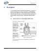
2 Description............................................................................................................... 9
2.1 Hale Valve Actuator System (SVS) ................................................................................... 9
Figure 2-1: SVS Valve Control.............................................................................................. 9
Pressure Switch (10 PSI / 0.7 BAR) ................................................................................................. 10
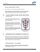
2.2 Class 1 (Intelli-Tank) Level Indicator.............................................................................. 10
Figure 2-2: Intelli-Tank 4-Light Indicator ............................................................................. 10
2.3 Driver Module, Harnesses and Relays ........................................................................... 10
“Fill Required Signal” – Driver Module.............................................................................................. 10
Relay Assembly ................................................................................................................................11
2.4 AUTOFILL Control Panels ............................................................................................... 11
AUTOFILL Control Panel .................................................................................................................11
Figure 2-3: AutoFill Control Panel AUTO / MANUAL.......................................................... 11
Toggle Switch.............................................................................................................................11
Indicator Light.............................................................................................................................12
MANUAL Control Panel .................................................................................................................... 12
Toggle Switch, Three-Position ...................................................................................................12
Figure 2-4: MANUAL Control Panel.................................................................................... 12
Indicator Lights........................................................................................................................... 12
3 Installation ............................................................................................................. 13
3.1 SVS Valve Actuator .......................................................................................................... 13
3.2 Pressure Switch Mounting .............................................................................................. 13
Figure 3-1: Pressure Switch Mounting................................................................................ 13
3.3 Control Panels .................................................................................................................. 13
Figure 3-2: Control Panel Cutouts - Manual, AutoFill and Water Level Gauge .................. 14
AutoFill Control Panels (2)................................................................................................................14
Water Level LED Gauge...................................................................................................................14
Relay Assembly and Power Distribution/Lighting Module ................................................................ 15
Wire Harness .................................................................................................................................... 15
AutoFill Selector Power Harness ......................................................................................................16
Figure 3-3: AutoFill Selector Harness Connection.............................................................. 16
Relay Assembly Power Harness ...................................................................................................... 16
Figure 3-4: Relay Assembly Power Connection .................................................................17