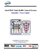
AutoFill-E Tank Refill Control System Installer / User Guide Hale Products Inc. ◆ A Unit of IDEX Corporation 700 Spring Mill Avenue ◆ Conshohocken, PA 19428 U.S.A. Telephone: 610-825-6300 ◆ FAX: 610-825-6440 Web......www.haleproducts.
NOTICE ! Hale Products, Inc. (Hale) cannot assume responsibility for product failure resulting from improper maintenance or operation. Hale is responsible only to the limits stated in the product warranty. Product specifications contained in this manual are subject to change without notice. All Hale products are quality components -- ruggedly designed, accurately machined, precision inspected, carefully assembled and thoroughly tested.
Table of Contents ❑ Contents Page AutoFill-E Tank Refill Installer / User Guide 1 Safety Precautions................................................................................................... 5 1.1 2 Guidelines ........................................................................................................................... 5 Description ............................................................................................................... 9 2.
❑ Table of Contents Contents - continued 3 Page Installation - continued 3.4 Driver Module ................................................................................................................... 17 Figure 3-5: Driver Module Layout ....................................................................................... 17 4 Calibration ............................................................................................................. 18 5 Operation ...............................
Safety Precautions 1 ❑ Safety Precautions IMPORTANT ! THE HALE “AUTOFILL - E” TANK REFILL CONTROL SYSTEM IS DESIGNED FOR OPTIMUM SAFETY OF ITS OPERATORS. FOR ADDED PROTECTION AND BEFORE ATTEMPTING INSTALLATION OR OPERATION PLEASE FOLLOW THE SAFETY GUIDELINES LISTED IN THIS SECTION AND ADHERE TO ALL WARNING, DANGER, CAUTION AND IMPORTANT NOTES FOUND WITHIN THIS GUIDE.
❑ Safety Precautions ❑ The installer is responsible for observing all instructions and safety precautions in his or her daily routine as dictated by regional safety ordinances or departmental procedures. ❑ DO NOT permanently remove or alter any guarding or insulating devices, or attempt to operate the system when these guards are removed. Make sure all access/service panels and covers are installed, closed and latched tight, where applicable.
Safety Precautions ❑ ❑ To prevent electrical shock always disconnect the primary power source before attempting to service any part of the Hale AutoFill-E system. ❑ All electrical systems have the potential to cause sparks during service. Take the necessary precautions to eliminate explosive or hazardous environments during any installation/service. ❑ Relieve all system pressure, then drain all foam concentrate and water from the system before servicing any of its component parts.
❑ Safety Precautions Notes ______________________________________________________________ ______________________________________________________________ ______________________________________________________________ ______________________________________________________________ ______________________________________________________________ ______________________________________________________________ ______________________________________________________________ ___________________________________________
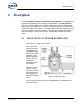
Introduction 2 ❑ Description The Hale AUTOFILL-E (Electric) Tank Refill Control System is a completely integrated and engineered system comprising of both Class 1 and Hale Products. The Class 1 “Driver Module” (p/n: 106877) is designed to output a “Fill Required” signal when the tank drops to 75% of FULL and to shut down the fill when the tank is within one-eighth of full capacity. The Intelli-Tank 4-LED Light Gauge and Alarm notify the operator of the tanks condition.
❑ Introduction Pressure Switch (10 PSI / 0.7 BAR) Also see Figure 3-1: “Pressure Switch Mounting” on page 13. The pressure switch ensures that 10 PSI (0.7 BAR) is available from the suction or INLET source for AutoFill operation. Pressure less than 10 PSI disables the AutoFill system and causes the SVS valve to CLOSE. 2.2 CLASS 1 (INTELLI-TANK) LEVEL INDICATOR (HALE P/N: 106299) Four (4) illuminating lights (RED) indicate the water level in the tank. (See Figure 2-2: “IntelliTank 4-Light Indicator.
Introduction ❑ A “FILL” required signal is then generated in the Class 1 Driver Module to begin the FILL process. The driver module incorporates an auto-fill function that, when activated, OPENS the SVS valve at less than 75% tank level and CLOSES the valve when the tank reaches the FULL point (approximately 1/8 of volume from FULL). An optional alarm is available and activates when the tank drops to 1/4 FULL, or if data is lost for more than ten seconds.
❑ Introduction Indicator Light The BLUE indicator illuminates when the toggle switch is in the AUTO position AND there is a minimum of 10 PSI (0.7 BAR) inlet pressure. (See Figure 2-3: “AutoFill Control Panel AUTO / MANUAL” on page 11.) If the toggle switch is in the AUTO position and the minimum inlet pressure of 10 PSI (0.7 BAR) is not available, the BLUE indicator does not illuminate and the AutoFill system does not function.
❑ Installer Installation and Calibration 3 Installation Refer to drawings Plate #: 1024A and Plate #: 1048A for additional installation, wiring and layout information. Both drawings are located at the back of this manual. 3.1 SVS VALVE ACTUATOR Detailed SVS Valve Actuator System installation instructions are found in a separate manual (Hale p/n: 029-0020-90-0). This manual is packaged with the Valve Actuator and is also available on the Hale web site: www.haleproducts.com/literature/manuals.
❑ Installer Installation and Calibration Figure 3-2: Control Panel Cutouts - Manual, AutoFill and Water Level Gauge AutoFill Control Panels (2) The two AutoFill control panels are mounted on the apparatus pump panel, with the supplied placards, as shown in Figure 3-2: “Control Panel Cutouts Manual, AutoFill and Water Level Gauge.
Installer Installation and Calibration ❑ Before mounting the display and adhering the label, insure that the unit is positioned correctly (TOP is up). Refer to separate manual “Intelli-Tank Water/Foam Tank Level Display,” p/n: 106759 (021502), located at the back of this manual and packaged with the unit. Before installation and operation, review this manual in its entirety. Relay Assembly and Power Distribution/Lighting Module Both units must be mounted within proximity of the apparatus main pump panel.
❑ Installer Installation and Calibration AutoFill Selector Power Harness ❑ Power Harness, 18” (0.5m) length, p/n: 513-0270-04-0 Before connecting this cable, inspect the seals in the connectors. If the seals are missing or damaged water can enter the connector causing pin and terminal corrosion, resulting in possible system failure. (See Figure 3-3: “AutoFill Selector Harness Connection.”) This line must be fused, connected to a 12VDC power, and minimum 20 amp circuit to meet NFPA specifications.
Installer Installation and Calibration ❑ To reduce RF / EM interference, the relay assembly power harness must be connected to a “clean” power source with NO other electrical equipment attached. (See Figure 3-4: “Relay Assembly Power Connection,” on page 17.) IMPORTANT ! DO NOT CONNECT POWER SUPPLY HARNESS TO A “LOAD SHEDDING SYSTEM.” Figure 3-4: Relay Assembly Power Connection 3.4 DRIVER MODULE The driver module is water tight and can be mounted any place away form large RF noise generators.
❑ Installer Installation and Calibration 4 Calibration Before placing the AUTOFILL System into service, it must be calibrated in accordance with the supplied manuals. The Intelli-Tank 4-Light Level Gauge requires calibration as detailed in the manual, p/n: 106759 (021502), packaged separately with the unit. The manual includes Calibration, Self-Test and Troubleshooting. Review this manual in its entirety before placing the system into operation.
❑ Operation 5 Operation The AUTOFILL system should receive its power from the down side of the main disconnect of the apparatus and is always operable while power is supplied to the pump panel. 5.1 AUTO MODE 1. Set the AutoFill select toggle switch to AUTO. The blue LED illuminates, providing there is at least 10 PSI (0.7 BAR) available. Note: If the minimum inlet pressure of 10 PSI (0.7 BAR) is not available, the BLUE indicator does not illuminate and the AutoFill system does not function.
❑ Operation CAUTION ! - continued A “LOW LEVEL” CONDITION CAUSES INSUFFICIENT WATER FLOW FOR CAFSPRO OPERATION; IN TURN, REDUCING THE EFFECTIVENESS OF THE FOAM CONCENTRATE. AN “OVERFILL” (TANK OVERFLOWS) IS VERY HAZARDOUS IN FREEZING WEATHER CONDITIONS. 1. Set the AUTOFILL select toggle switch to MANUAL (Operator Control). The BLUE LED turns OFF. 2.
❑ Routine Maintenance 6 Routine Maintenance WARNING! BEFORE BEGINNING ANY INSPECTION OR MAINTENANCE OF THIS EQUIPMENT, VERIFY THAT THE PRESSURE HAS BEEN RELEASED FROM THE SYSTEM. LOCK OUT THE EQUIPMENT IN ACCORDANCE WITH THE MANUFACTURER’S RECOMMENDATIONS AND YOUR DEPARTMENTAL REGULATIONS / PROCEDURES. OPEN THE DISCHARGE VALVES AND REMOVE THE SUCTION TUBE CAPS AND DISCHARGE VALVE CAPS TO RELEASE ANY RESIDUAL PRESSURE.
❑ Routine Maintenance Notes ____________________________________________________________________ ____________________________________________________________________ ____________________________________________________________________ ____________________________________________________________________ ____________________________________________________________________ ____________________________________________________________________ ____________________________________________________________________
Troubleshooting 7 ❑ Troubleshooting 7.1 TROUBLESHOOTING Troubleshooting is described in the following separate manuals for the Intelli-Tank high Current 4-Light Driver Module and the Intelli-Tank Water/ Foam Tank Level Display. A copy of these manuals is located at the back of this manual and an additional copy is packaged separately with the units. Intelli-Tank Water/Foam Tank Level Display ............ p/n: 106759 (021502) Intelli-Tank Driver Module ......................................
❑ Troubleshooting Notes ____________________________________________________________________ ____________________________________________________________________ ____________________________________________________________________ ____________________________________________________________________ ____________________________________________________________________ ____________________________________________________________________ ____________________________________________________________________ ____
Limited Warranty Express Warranty EXPRESS WARRANTY: Hale Products, Inc. (HALE) hereby warrants to the original Buyer that products manufactured by Hale are free of defects in material and workmanship for one (1) year. The “Warranty Period” commences on the date the original Buyer takes delivery of the product from the manufacturer. LIMITATIONS: Hale’s obligation is expressly conditioned on the Product being: ● Subjected to normal use and service.
Hale Products, Inc. A Unit of IDEX Corporation 700 Spring Mill Avenue Conshohocken, PA 19428 U.S.A. Telephone ...................610-825-6300 Fax .. ...........................610-825-6440 Web...........www.haleproducts.
AutoFill-E Tank Refill Control System Installer / User Guide Drawing and Manual Package Hale Products Inc. ◆ A Unit of IDEX Corporation 700 Spring Mill Avenue ◆ Conshohocken, PA 19428 U.S.A. Telephone: 610-825-6300 ◆ FAX: 610-825-6440 Web........www.haleproducts.
Contents 8 Drawings / Manuals.................................................................Plate Number Drawings AutoFill “E” Control System .........................................................................................................1024A AutoFill “E” Control System Installation Drawing.........................................................................1048A Manuals Torrent SVS Valve, under separate cover .....................................................................
Notes ________________________________________________________________________________________ ________________________________________________________________________________________ ________________________________________________________________________________________ ________________________________________________________________________________________ ________________________________________________________________________________________ ________________________________________________________
Notes ________________________________________________________________________________________ ________________________________________________________________________________________ ________________________________________________________________________________________ ________________________________________________________________________________________ ________________________________________________________________________________________ ________________________________________________________
Intelli-Tank Water/foam tank level display utilizing a 0-5 PSI transducer Contents ………………………………………………….. 1 Overview ………………………………………………….. 2 Operation ………………………………………………….. 3 Installation ………………………………………………….. 5 Wiring ………………………………………………….. 7 Calibration ………………………………………………….. 9 Dim function ………………………………………………….. 11 Self test ………………………………………………….. 11 Passwords ………………………………………………….. 12 Troubleshooting …………………………………………………..
The Intelli-Tank 4 light tank level is designed to display a liquid’s volume to an eighth of a tank level accuracy through 180-degree viewable ultra-bright LEDs. The unit set as a Master uses a 0 – 5 PSI pressure transducer to obtain tank level information and then relays that information along the data line to units set as Remotes. Multiple Remote units can be linked to the Master tank level unit.
When the unit is first powered up the LEDs will cycle on individually starting with the EMPTY (bottom) LED and then the LEDs will show current status. • A Master unit properly connected to a functioning transducer will display current tank level information. • A Master unit not connected to a pressure transducer will alternately flash the bottom two LEDs. • A Remote unit connected to a Master unit (through the 1-wire data line) will mimic the Master unit’s LED condition and flash rate.
Miscellaneous indications: Condition LED 4 LED 3 LED 2 LED 1 Invalid calibration AlternaFLASH AlternaFLASH EEPROM error AlternaFLASH AlternaFLASH Signal voltage above AlternaFLASH AlternaFLASH 4.8V Signal voltage below AlternaFLASH AlternaFLASH .4V Remote “NO DATA” AlternaFLASH AlternaFLASH User Error (wave off) 4 quick cycles ON ON ON ON The tank level has two flash rates: FAST (1.6Hz) and SLOW (.8Hz). AlternaFLASH flashes two lights alternately at the SLOW flash rate.
Intelli-Tank display The display requires a cutout as shown. The unit is water tight and may be mounted in any location on the operator’s panel. Outer bezel dimensions.
Before mounting the display and adhering the label insure that the unit is situated correctly (TOP is UP). Refer to the drawing for orientation. Pressure Transducer The transducer has a ¼” NPT mount and must be mounted vertically as depicted to insure an accurate reading.
Power and Ground It is imperative that a system utilizing Master and Remote tank level units connected by the 1-wire data line have a common ground. Pin 1 Vehicle power Pin 2 Ground Dim Function The LEDs on the tank level unit can be dimmed to a user selectable dim setting by applying vehicle voltage to the Dim display Input.
Typical installation layout.
The Intelli-Tank display can be calibrated three different ways: 2-point (level calibration), 5-point and 9-point (volume calibration). To enter calibration mode use a magnet and activate the magnetic switches in the order of the appropriate password. When a magnetic switch is activated the display will indicate which switch was activated (Left = upper two LEDs, Right = lower two LEDs) for approximately half a second and then the display will go blank.
The unit will respond by flashing the two center LEDs the same number of times as the desired calibration. The unit will then indicate the level to be calibrated by lighting the proper LEDs for that level starting with empty (see page 3, tank level indications). When the tank is filled to the proper level for calibration (dictated by the LEDs) activate the RIGHT switch to store that point. The unit will flash the top LED and then set the LEDs for the next calibration point.
Dimming the Display The display can be dimmed by applying VIGN to pin 3 (Dim Display input). To select the dim level of the display use the magnetic switches to enter the password RLLR LLLR all of the LEDs will come on. Hold the magnet against the RIGHT switch and the display will either brighten or dim. Release the magnet and again hold it against the RIGHT switch and the display’s brightness will move in the opposite direction. When the dim level is at the desired point activate the LEFT switch.
RLLR LLRL 2 point calibration RLLR LRLR 5 point calibration RLLR RLLR 9 point calibration RLLR LLRR Self test RLLR LLLL Configure unit as Remote unit RLLR LLLR Configure dim level Software revision check Hold a magnet on the LEFT magnetic switch while powering the unit. The LEDs will display the software revision. (Use the chart below to decipher). Example. (LED 4 – OFF, LED 3 – ON, LED 2 – OFF, LED 1 – ON) = Ver 1.
Condition Evaluate Bottom two LEDs alternate flashing. Check transducer wiring. Ensure +5V at pin A, ground at pin B and at least .4V at pin C (Signal). Unit fails self test, LED 1 flashing. Top two LEDs alternate flashing. Check transducer wiring. Ensure +5V at pin A, ground at pin B and no more than 4.8V at pin C (Signal). Unit fails self test, LED 1 on. Middle two LEDs alternate flashing. Perform self test. If it fails with LED 3 on replace unit. Outer two LEDs alternate flashing.
Condition Evaluate Check for large noise spikes on the data line. The bottom two LEDs are on and Insure that the unit’s ground potential is the same as the Master’s. occasionally they go Insure that the data line is not chaffed and making contact with out and the top two other electrical wires. flash and then return to the bottom two LEDs on (or viceversa). (REMOTE). The points calibrated seemed to have changed. Self test the unit to check for any malfunctions. Unit will not dim display.
Intelli-Tank High current 4 light remote driver module with auto refill and alarm Contents ………………………………………………….. 1 Overview ………………………………………………….. 2 Operation ………………………………………………….. 3 Wiring ………………………………………………….. 5 Specifications ………………………………………………….. 8 Troubleshooting …………………………………………………..
The Intelli-Tank Driver module utilizes the 1-wire data line to receive tank level information from a Master 4 light tank level display (C1-PN 106299 or 106296) and then mimics the Master’s display with its high current outputs. The module also incorporates an auto-refill function that, when activated, turns on the fill output at less than ¾ tank level and turns it off when the tank reaches the FULL point.
When the unit is first powered up the lights will cycle on individually starting with the EMPTY (output 1) light and then the lights will show the current status. • A Module connected to a Master unit (through the 1-wire data line) will mimic the Master unit’s LED condition and flash rate. • A Module not connected to a Master unit will alternately flash the upper two lights and the lower two lights. This indicates a “no data” condition.
The auto-fill function will energize the fill output when the tank level is at or below ¾ and de-energize when the Master display reads FULL. Auto-fill will also deenergize the fill output and turn off the auto-fill status light if there is no data being received on the data line from the Master display (serial error) or if a transducer error high or low (range error) is encountered. 4 Outputs for the level lights Four outputs are available to drive external lights to indicate tank level.
Driver Module The module is water tight and can be mounted any place away from large RF noise generators.
Typical installation Connector detail Intelli-Tank Manual (106759) 12-15-03 –6– Class 1
Power and Ground It is imperative that the driver module and the Master tank level have a common ground. Stud Vehicle power (12/24VDC) Pin 12 Ground High Current Outputs (7.
Parameter Value Unit +10 to +32 VDC @ 13.8VDC 44 mA @ 27.6VDC 55 mA -40 to 85 °C Alarm output 250 mA Auto-fill status light output 250 mA Fill output 250 mA External light outputs 7.
Condition Evaluate Bottom two lights alternate flashing. Master tank level display’s transducer signal voltage is below .4VDC. Check transducer wiring to master tank level display. Top two lights alternate flashing. Master tank level display’s transducer signal voltage is above 4.80VDC. Check transducer wiring to master tank level display. Bottom two and Upper two lights alternate flashing. Remote driver module is not receiving data from the master tank level display.