6/26/2003 TM FoamLogix MODEL 3.3 AND 5.
ROTARY GEAR PUMP ELECTRONIC FOAM PROPORTIONING SYSTEM TABLE OF CONTENTS Chapter Title Page SECTION I: DESCRIPTION SAFETY .................................................................................................................................... I-1 SYSTEM DESCRIPTION ............................................................................................................ I-3 SYSTEM SPECIFICATIONS .................................................................................................
TM FoamLogix MODEL 3.3 AND 5.0 ROTARY GEAR PUMP ELECTRONIC FOAM PROPORTIONING SYSTEM DESCRIPTION, INSTALLATION AND OPERATION MANUAL SECTION I DESCRIPTION NOTICE: This manual section provides a general description of the Hale foam proportioning system along with guidelines for designing and ordering a complete system. This manual section can be used as a stand alone section or in conjunction with other sections of the complete manual. HALE PRODUCTS, INC.
ROTARY GEAR PUMP ELECTRONIC FOAM PROPORTIONING SYSTEM SAFETY Hale Foam systems are designed to provide reliable and safe foam concentrate injection. Before installing or operating a Hale Foam system read all safety precautions and follow carefully to ensure proper installation and personnel safety. WARNINGS 1. Do not permanently remove or alter any guard or insulating devices or attempt to operate the system when these guards are temporarily removed. 2.
ROTARY GEAR PUMP ELECTRONIC FOAM PROPORTIONING SYSTEM NOTES 1. Check all hoses for weak or worn conditions after each use. Ensure that all connections and fittings are tight and secure. 2. Ensure that the electrical source of power for the unit is a negative ground DC system, of correct input voltage, with a reserve minimum current available to drive the system. 3. The in-line strainer/valve assembly is a low pressure device and WILL NOT withstand flushing water pressure.
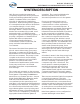
ROTARY GEAR PUMP ELECTRONIC FOAM PROPORTIONING SYSTEM SYSTEM DESCRIPTION Hale Foam proportioning systems are completely engineered, factory matched foam proportioning systems that provide reliable, consistent foam concentrate injection for Class A and Class B foam operations. Hale FoamLogix Foam systems accurately deliver from 0.1% to 10.0% foam concentrate through a check valve/ injector fitting directly into the water discharge stream.
ROTARY GEAR PUMP ELECTRONIC FOAM PROPORTIONING SYSTEM Table 1. Maximum Foam Solution Flows WATER FLOW MODEL 3.3 MODEL 5.0 FOAM CONCENTRATE GPM (%) 0.1 0.2 0.3 0.5 1 3 6 LPM GPM LPM 3300 12491 5000 18925 1650 6245 2500 9463 1100 4164 1667 6310 660 2498 1000 3785 330 1249 500 1893 110 416 167 632 55 208 83 314 concentrate tanks. Examples of the various Hale Foam system configurations are shown in figures 1-1 through 1-7 at the end of this section.
ROTARY GEAR PUMP ELECTRONIC FOAM PROPORTIONING SYSTEM Ordering of Hale Foam systems is simple. Using the current Hale FoamLogix Foam System Price List and Order Form helps ensure a complete matched system is provided to the end user. Use the following procedure when ordering a Hale FoamLogix Foam system. Following all the steps ensures a complete system will be ordered: 1. Check Hale Foam system product information update (Bulletin 961) for the latest information and advice for foam system selection. 2.
ROTARY GEAR PUMP ELECTRONIC FOAM PROPORTIONING SYSTEM HALE FOAM SYSTEM SPECIFICATIONS Foam Pump................................................................................. Rotary Gear Positive Displacement Rated Foam Concentrate Output Model 3.3 ........................................................................................................ 3.3 GPM (12 LPM) Model 5.0 ........................................................................................................ 5.
ROTARY GEAR PUMP ELECTRONIC FOAM PROPORTIONING SYSTEM MODEL MODEL MODEL MODEL MODEL MODEL 5.0: 3.3: 5.0: 3.3: 5.0: 3.3: 25.37 25.12 24.74 24.94 23.70 23.45 IN. IN. IN. IN. IN. IN. (644 (638 (628 (622 (602 (596 MM) MM) MM) MM) MM) MM) MODEL MODEL MODEL MODEL 5.0: 3.3: 5.0: 3.3: 21.88 21.63 20.63 20.38 IN. IN. IN. IN. (555 (549 (524 (518 MM) MM) MM) MM) BYPASS HANDLE: BYPASS POSITION BYPASS HANDLE: INJECT POSITION INJECT PORT: ½ INCH NPT BYPASS PORT: ½ INCH NPT MODEL 5.0: 19.07 IN.
ROTARY GEAR PUMP ELECTRONIC FOAM PROPORTIONING SYSTEM SYSTEM CONFIGURATION Hale Foam Proportioner System Model (Model 3.3 or Model 5.0) All Hale Foam systems include: Foam Pump/Motor Assembly, Control Unit, Control Cable and Check Valve/Injector Fitting FOAMLOGIX MOD EL PAR T N U MB ER FOAMLOGIX 5.0 W/12 VD C MOTOR 501-3130-15-0 FOAMLOGIX 5.0 W/24 VD C MOTOR 501-3130-24-0 FOAMLOGIX 3.3 W/12 VD C MOTOR 501-3120-15-0 FOAMLOGIX 3.
ROTARY GEAR PUMP ELECTRONIC FOAM PROPORTIONING SYSTEM Dual Foam Concentrate Tank System Options Panel Switch/Indicator Light Placard Assembly Optional Color Coded Air Connection Harness (P/N 507-0380-00-0) Foam Pump/Motor Assembly with Air Dual Tank (ADT) Selector (P/N 538-1640-02-0) Manual Dual Tank (MDT ΙΙ) Selector and Wiring Harness (P/N 538-1490-11-0) Dual Tank Instruction Placard/System Diagram (P/N 101-1631-07-0) Section I: Description MDT ΙΙ Wiring Harness Extension (P/N 513-0320-02-0) Ι-9
ROTARY GEAR PUMP ELECTRONIC FOAM PROPORTIONING SYSTEM Single Foam Concentrate Tank Options Manual Single Tank (MST) Selector Provides FoamPump Flushing Capabilities for a Single Tank System (P/N 538-1490-12-0) MST Wiring Harness (P/N 513-0320-04-0) Single Tank Instruction Placard/System Diagram (P/N 101-1631-12-0) MST Wiring Harness Extension 72 inches (1829 mm) long (P/N 513-0320-07-0) Foam Concentrate Strainers In-Line Strainer/Valve Assembly (P/N 510-0190-01-0) (Do Not Use If Subject to Flushing W
ROTARY GEAR PUMP ELECTRONIC FOAM PROPORTIONING SYSTEM Low Tank Level Sensor Options (One Low Tank Level Sensor is Required for Each Foam Tank) Side Mount Low Tank Level Sensor (P/N 200-2110-02-0) (½ Inch NPT Threaded Bushing to Mount From Outside Foam Tank) Brass Bottom Mount Low Tank Level Sensor (P/N 200-2110-04-0) (1 Inch NPT Threaded Bushing to Mount From Outside Foam Tank) Section I: Description Top Mount Low Tank Level Sensor Assembly (P/N 200-2110-06-0) (Extends From 2-½ Feet to 5 Feet Long.
ROTARY GEAR PUMP ELECTRONIC FOAM PROPORTIONING SYSTEM Flowsensors Each Hale foam system requires a flowsensor to operate. Pipe size must be selected based on the minimum and maximum water flow in the foam capable discharge. Following is a list of pipe size and rated flow range along with flowsensor saddle clamp part number: In all instances a weld fitting may be substituted for the saddle clamp.
ROTARY GEAR PUMP ELECTRONIC FOAM PROPORTIONING SYSTEM Check Valve Manifolds The check valve manifolds include Flowsensor, Check Valve/Injector fitting and single or dual waterway check valve flappers. End connections for the manifolds are 3 inch victaulic.
ROTARY GEAR PUMP ELECTRONIC FOAM PROPORTIONING SYSTEM Check Valves, Flanges and Gaskets 3 Inch "115" Check Valve (P/N 038-1570-00-0) T H R E AD S PAR T N U MB ER 3 INC H NPT 115-0080-00-0 2-1/2 INC H NPT 115-0070-00-0 2 INC H NPT 115-0060-00-0 BLANK 115-0050-00-0 4 Inch "2433D" Check Valve (P/N 038-1570-04-0) T H R E AD S PAR T N U MB ER 4 INC H NPT 115-0040-00-0 3 INC H NPT 115-0030-00-0 2-1/2 INC H NPT 115-0020-00-0 BLANK 115-0010-00-0 Type 115 Flange Use 3 and 2-½ inch NPT with 3
ROTARY GEAR PUMP ELECTRONIC FOAM PROPORTIONING SYSTEM Elbows and Mini Manifold Close Fit Flanged Elbow (P/N 098-0140-00-0) Close Fit Flanged Elbow (P/N 098-0190-00-0) 115 flange inlet with 3 inch Victaulic outlet. 2433D flange inlet with 3 inch female NPT and 4 inch Victaulic outlet. Close Fit Flanged Elbow (P/N 098-0050-00-0) Close Fit Flanged Elbow (P/N 098-0020-00-0) 115 flange inlet with 2-½ inch female NPT outlet. 115 flange inlet with 115 flange outlet.
ROTARY GEAR PUMP ELECTRONIC FOAM PROPORTIONING SYSTEM TOP MOUNT FOAM TANK LOW LEVEL SENSOR OPTION SIDE MOUNT FOAM TANK LOW LEVEL SENSOR OPTION FOAM TANK BOTTOM MOUNT FOAM TANK LOW LEVEL SENSOR OPTION FOAM TANK DRAIN VALVE IN-LINE FOAM STRAINER/ VALVE ASSEMBLY FLUSHING WATER SUPPLY FOAM PUMP AND MOTOR ASSEMBLY FLOWSENSOR CORDSET CONTROL CORDSET FOAM INJECTION HOSE BYPASS VALVE CONTROL UNIT BYPASS HOSE DISTRIBUTION BOX CHECK VALVE INJECTOR FITTING HALE FLOWSENSOR PADDLE WHEEL MOUNTED IN SADDLECLAMP
ROTARY GEAR PUMP ELECTRONIC FOAM PROPORTIONING SYSTEM TOP MOUNT FOAM TANK LOW LEVEL SENSOR OPTION FOAM TANK SIDE MOUNT FOAM TANK LOW LEVEL SENSOR OPTION BOTTOM MOUNT FOAM TANK LOW LEVEL SENSOR OPTION FOAM TANK DRAIN VALVE IN-LINE FOAM STRAINER/ VALVE ASSEMBLY MST SELECTOR VALVE FOAM PUMP AND MOTOR ASSEMBLY CONTROL CORDSET CONTROL UNIT FLUSHING WATER SUPPLY BYPASS VALVE BYPASS HOSE FOAM INJECTION HOSE DISTRIBUTION BOX HALE FLOWSENSOR PADDLE WHEEL MOUNTED IN SADDLECLAMP FIRE PUMP WATERWAY CHECK VA
ROTARY GEAR PUMP ELECTRONIC FOAM PROPORTIONING SYSTEM FOAM TANK FOAM TANK SHUTOFF VALVE FOAM TANK DRAIN VALVE MST SELECTOR VALVE FS-15 OR FS-25 PANEL MOUNTED FOAM STRAINER FOAM INJECTION HOSE CONTROL CORDSET FOAM PUMP AND MOTOR ASSEMBLY CONTROL UNIT BYPASS VALVE DISTRIBUTION BOX FLUSHING WATER SUPPLY FLOWSENSOR CORDSET BYPASS HOSE CHECK VALVE INJECTOR HALE FITTING FLOWSENSOR PADDLE WHEEL MOUNTED IN SADDLECLAMP FIRE PUMP WATERWAY CHECK VALVE WATERWAY CHECK VALVE FOAM SOLUTION DISCHARGE(S) Fig
ROTARY GEAR PUMP ELECTRONIC FOAM PROPORTIONING SYSTEM SIDE MOUNT FOAM TANK LOW LEVEL SENSOR OPTION TOP MOUNT FOAM TANK LOW LEVEL SENSOR OPTION TOP MOUNT FOAM TANK LOW LEVEL SENSOR OPTION BOTTOM MOUNT FOAM TANK LOW LEVEL SENSOR OPTION FOAM TANK A BOTTOM MOUNT FOAM TANK LOW LEVEL SENSOR OPTION SIDE MOUNT FOAM TANK LOW LEVEL SENSOR OPTION FOAM TANK B FOAM TANK DRAIN VALVE IN-LINE FOAM STRAINER/ VALVE ASSEMBLY FOAM TANK DRAIN VALVE MDT II SELECTOR VALVE CONTROL CORDSET CONTROL UNIT IN-LINE FOAM STR
ROTARY GEAR PUMP ELECTRONIC FOAM PROPORTIONING SYSTEM TOP MOUNT FOAM TANK LOW LEVEL SENSOR OPTION TOP MOUNT FOAM TANK LOW LEVEL SENSOR OPTION FOAM TANK B FOAM TANK A FOAM TANK SHUTOFF VALVE SIDE MOUNT FOAM TANK LOW LEVEL SENSOR OPTION SIDE MOUNT FOAM TANK LOW LEVEL SENSOR OPTION BOTTOM MOUNT FOAM TANK LOW LEVEL SENSOR OPTION FOAM TANK DRAIN VALVE BOTTOM MOUNT FOAM TANK LOW LEVEL SENSOR OPTION FOAM TANK DRAIN VALVE FOAM TANK SHUTOFF VALVE MDT II SELECTOR VALVE CONTROL CORDSET FS-15 OR FS-25 PANEL
ROTARY GEAR PUMP ELECTRONIC FOAM PROPORTIONING SYSTEM FOAM TANK A FOAM TANK B FOAM TANK DRAIN VALVE IN-LINE FOAM STRAINER/ VALVE ASSEMBLY ADT SELECTOR SWITCH AND INDICATOR LIGHTS FOAM TANK DRAIN VALVE IN-LINE FOAM STRAINER/ VALVE ASSEMBLY FOAM PUMP WITH ADT CONTROL UNIT FLOWSENSOR CORDSET FOAM INJECTION HOSE CONTROL CORDSET DISTRIBUTION BOX CHECK VALVE INJECTOR FITTING BYPASS VALVE FLUSHING WATER SUPPLY HALE FLOWSENSOR PADDLE WHEEL MOUNTED IN SADDLECLAMP BYPASS HOSE FIRE PUMP WATERWAY CHECK
ROTARY GEAR PUMP ELECTRONIC FOAM PROPORTIONING SYSTEM FOAM TANK B FOAM TANK A FOAM TANK DRAIN VALVE FOAM TANK SHUTOFF VALVE FOAM TANK DRAIN VALVE FOAM TANK SHUTOFF VALVE FS-15 PANEL MOUNTED FOAM STRAINER FS-25 PANEL MOUNTED FOAM STRAINER ADT SELECTOR SWITCH AND INDICATOR LIGHTS CONTROL UNIT FOAM PUMP WITH ADT CONTROL CORDSET FLOWSENSOR CORDSET FOAM INJECTION HOSE BYPASS VALVE BYPASS HOSE DISTRIBUTION BOX CHECK VALVE INJECTOR FITTING FLUSHING WATER SUPPLY HALE FLOWSENSOR PADDLE WHEEL MOUNTED I
TM FoamLogix MODEL 3.3 AND 5.0 ROTARY GEAR PUMP ELECTRONIC FOAM PROPORTIONING SYSTEM DESCRIPTION, INSTALLATION AND OPERATION MANUAL SECTION II INSTALLATION NOTICE: This manual section provides information to assist the OEM with installation and initial setup of Hale foam proportioning systems on an apparatus. This manual section can be used as a stand alone section or in conjunction with other sections of the complete manual. HALE PRODUCTS, INC.
ROTARY GEAR PUMP ELECTRONIC FOAM PROPORTIONING SYSTEM SAFETY Hale FoamLogix systems are designed to provide reliable and safe foam concentrate injection. Before installing or operating a Hale FoamLogix system read all safety precautions and follow carefully to ensure proper installation and personnel safety. WARNINGS 1. Do not permanently remove or alter any guard or insulating devices or attempt to operate the system when these guards are temporarily removed. 2.
ROTARY GEAR PUMP ELECTRONIC FOAM PROPORTIONING SYSTEM NOTES 1. Check all hoses for weak or worn conditions after each use. Ensure that all connections and fittings are tight and secure. 2. Ensure that the electrical source of power for the unit is a negative ground DC system, of correct input voltage, with a reserve minimum current available to drive the system. 3. The in-line strainer/valve assembly is a low pressure device and WILL NOT withstand flushing water pressure.
ROTARY GEAR PUMP ELECTRONIC FOAM PROPORTIONING SYSTEM APPARATUS INSTALLATION PLANNING Differences in apparatus plumbing and foam system configuration make it impractical to show exactly how each Hale FoamLogix system is installed on a particular apparatus. The information contained in this section, however, will apply to most situations and should be used when designing and installing a Hale FoamLogix system.
ROTARY GEAR PUMP ELECTRONIC FOAM PROPORTIONING SYSTEM connections, tank drainage and proper fill openings per NFPA requirements. FOAM CONCENTRATE STRAINER: Determine a location on the apparatus to mount the foam strainer. CAUTION: The in-line strainer/valve assembly is a low pressure device and WILL NOT withstand flushing water pressure.
ROTARY GEAR PUMP ELECTRONIC FOAM PROPORTIONING SYSTEM INSTALLER SUPPLIED COMPONENT RECOMMENDATIONS Due to the many differences in apparatus configuration and apparatus design requirements the Hale FoamLogix system installer must supply components such as mounting brackets, piping, hoses, fittings and some electrical wiring. The following guidelines are recommendations for selection of these additional components for a complete system installation.
ROTARY GEAR PUMP ELECTRONIC FOAM PROPORTIONING SYSTEM The foam pump discharge port and check valve injector fitting connection port have ½ inch NPT threads. Hoses and fittings of ½ inch (13 mm) minimum inside diameter rated at 500 PSI (34 BAR) working pressure or maximum discharge pressure of the fire pump must be used. Fittings and hoses must be compatible with all foam agents to be used. RECOMMENDED COMPONENTS: Hose: Aeroquip 2580-10 or Equivalent Reinforced Hydraulic Hose.
ROTARY GEAR PUMP ELECTRONIC FOAM PROPORTIONING SYSTEM Some installations may require higher flows and larger diameter piping. Use a Hale 4 inch 2433 flange type check valve (Hale P/N 038-1570-04-0) for these installations. This check valve has an 8 bolt, 5-¾ inch bolt circle and will fit pump discharge openings and flanges that have this configuration. The Hale 2433 check valve has a pressure rating of 500 PSI (34 BAR) and a flow rating of 1250 GPM (4731 LPM).
ROTARY GEAR PUMP ELECTRONIC FOAM PROPORTIONING SYSTEM FoamLogix when the main apparatus electrical system is energized and the pump is in gear. Use of a solenoid with a 200 AMP peak, 100 AMP continuous rating is recommended. Figure 2-1 shows the recommended wiring of this relay. equipment. The ground strap should be a minimum of 1-¼ inches (32 mm) wide and be no longer than 18 inches (457 mm). The ground strap must have soldered flat lug ends with 5/16 inch (8 mm) diameter holes.
ROTARY GEAR PUMP ELECTRONIC FOAM PROPORTIONING SYSTEM FOAM PUMP MOUNTING Position the foam pump and motor assembly in the desired location on the apparatus. When installing the foam pump and motor assembly, the assembly should be kept in a horizontal position with the base plate on the bottom (see figure 2-2). Although the system is sealed and designed to be resistant to the harsh environment of fire fighting apparatus, a compartment with easy operator access is the recommended installation location.
ROTARY GEAR PUMP ELECTRONIC FOAM PROPORTIONING SYSTEM MODEL MODEL MODEL MODEL 5.0: 3.3: 5.0: 3.3: 22.00 21.75 19.07 18.82 IN. IN. IN. IN. (559 (552 (484 (478 MM) MM) MM) MM) 6.02 IN. (153 MM) 9.43 IN. (240 MM) ¾ INCH NPT SUCTION HOSE CONNECTION ½ INCH NPT INJECT HOSE CONNECTION 2.58 IN. (66 MM) ½ INCH NPT BYPASS HOSE CONNECTION Figure 2-3.
ROTARY GEAR PUMP ELECTRONIC FOAM PROPORTIONING SYSTEM MODEL MODEL MODEL MODEL MODEL MODEL 5.0: 3.3: 5.0: 3.3: 5.0: 3.3: 25.37 25.12 24.74 24.94 23.70 23.45 IN. IN. IN. IN. IN. IN. (644 (638 (628 (622 (602 (596 MM) MM) MM) MM) MM) MM) MODEL MODEL MODEL MODEL 5.0: 3.3: 5.0: 3.3: 21.88 21.63 20.63 20.38 IN. IN. IN. IN. (555 (549 (524 (518 MM) MM) MM) MM) BYPASS HANDLE: BYPASS POSITION BYPASS HANDLE: INJECT POSITION INJECT PORT: ½ INCH NPT BYPASS PORT: ½ INCH NPT MODEL 5.0: 19.07 IN.
ROTARY GEAR PUMP ELECTRONIC FOAM PROPORTIONING SYSTEM PLUMBING COMPONENT INSTALLATION Hale FoamLogix System plumbing diagrams are located at the end of this manual section. The diagrams provide recommended guidelines for the installation of system components that handle water, foam concentrate and foam solution. The sequence in which the plumbing installation is completed depends on the individual installation.
ROTARY GEAR PUMP ELECTRONIC FOAM PROPORTIONING SYSTEM Figure 2-7 shows a suggested installation arrangement using Hale 4 inch check valves, Hale 2433 flanges and 4 inch pipe. WATERWAY CHECK VALVES Check valves in the waterway, rated at 500 PSI (34 BAR), are required to keep foam solution out of the main pump and allow pump priming without drawing foam into the piping.
ROTARY GEAR PUMP ELECTRONIC FOAM PROPORTIONING SYSTEM on the flowsensor outlet. In the short length of reduced pipe pressure loss will be minimal and there will be minimal pressure loss through elbows and fittings. Figure 2-9 shows a typical reduced piping run installation. Excessive turbulence in the flowsensor may produce unstable and inaccurate flow readings. The length of straight pipe prior to the flowsensor must be sufficient to reduce the turbulence in the pipe.
ROTARY GEAR PUMP ELECTRONIC FOAM PROPORTIONING SYSTEM either direction for proper operation. CORRECT WATER INLET AT LEAST 5X THE PIPE DIAMETER BETWEEN VALVE OR FITTING AND FLOWSENSOR FOAM PUMP FLUSH SYSTEM VALVE OR FITTING AFTER FLOWSENSOR INCORRECT WATER INLET VALVE OR FITTING BEFORE FLOWSENSOR WITH LESS THAN 5X THE PIPE DIAMETER BETWEEN Figure 2-10. Flowsensor Placement For proper installation, the flowsensor requires the use of a spacer and eight stainless steel internal hex head screws.
ROTARY GEAR PUMP ELECTRONIC FOAM PROPORTIONING SYSTEM SENSOR O-RINGS SADDLE CLAMP 1 inch (25 mm) or 1-1/4 inch (32 mm) inside diameter hose depending on the viscosity of foam concentrates used. (See figure 212) Generally ¾ inch inside diameter hose will be used for Class A foam and 1 inch inside diameter hose will be used for Class B foams. For high viscosity Class B foam concentrates it may be necessary to use 11/4 or 1-1/2 inside diameter hose.
ROTARY GEAR PUMP ELECTRONIC FOAM PROPORTIONING SYSTEM 1-1/4 INCH NPT X 1-1/4 INCH HOSE BARB (Use on each end for Class B foam concentrates) STRAINER MOUNTING BRACKET 2 INCHES (51 mm) MINIMUM CLEARANCE ABOVE FOR VALVE OPERATION FOAM CONCENTRATE OUTLET FOAM CONCENTRATE INLET 1-1/4 INCH NPT X 1 INCH HOSE BARB (Use on each end for Class B foam concentrates) STRAINER SERVICE VALVE (Shown in open position.
ROTARY GEAR PUMP ELECTRONIC FOAM PROPORTIONING SYSTEM inlet of the Hale MDT ΙΙ, Hale MST or foam concentrate pump or correct fitting on Hale ADT. FS SERIES STRAINER When a pressurized water flush is provided to the strainer from one of the discharges the use of Hale FS series strainers is required. The plumbing exposed to the flush water pressure must be rated at or above the operating pressure of all other discharge plumbing components.
ROTARY GEAR PUMP ELECTRONIC FOAM PROPORTIONING SYSTEM holes for mounting the foam strainer. The holes for the FS15 strainer mounting screws are 9/32 inch (7 mm) and the holes for FS25 strainer screws are 11/32 inch (9 mm) diameter. Additionally a hole of sufficient size for the cap threads to clear the panel is required. [FS15 strainer 2.13 inches (54 mm) and FS25 strainer 3.38 inches (86 mm)] 4. Select appropriate fittings for attachment of the hoses to the strainer.
ROTARY GEAR PUMP ELECTRONIC FOAM PROPORTIONING SYSTEM ½ INCH NPT THREADS (FOAM CONCENTRATE INLET) CHECK VALVE INJECTOR FITTING 1 INCH NPT THREADS BYPASS HOSE CONNECTION HALE MANIFOLD, PIPE TEE OR WELD BOSS ON PIPE Figure 2-17. Check Valve Injector Fitting Installation inch NPT threaded connection on the Hale mini manifold, a pipe tee or a 1 inch NPT weld fitting installed in the discharge piping of the fire pump (see figure 2-17).
ROTARY GEAR PUMP ELECTRONIC FOAM PROPORTIONING SYSTEM foam tank or to assist in priming of the foam pump. The hose from the BYPASS port must be long enough to reach a container outside the truck. This hose must be coiled for storage when not in use. ACORN NUT HANDLE HANDLE TANG If the handle or placard is removed from the bypass valve for repairs or to facilitate remote mounting make sure they are installed on the valve correctly.
ROTARY GEAR PUMP ELECTRONIC FOAM PROPORTIONING SYSTEM indicated in figure 2-21. A color coded decal attached to the ADT valve assembly along with an optional color coded air hose harness simplifies air hose connections. If the optional air hose harness is not used ¼ inch inside diameter air brake tubing can ΙΙ-22 be substituted. Make sure the air brake tubing selected has the proper DOT approval.
ROTARY GEAR PUMP ELECTRONIC FOAM PROPORTIONING SYSTEM AIR OUT A (GREEN) TANK A INDICATOR AIR IN (BLACK) SELECTOR SWITCH TANK B INDICATOR ELECTRICAL HARNESS AIR OUT B (RED) ADT PANEL PLACARD SIDE VIEW PANEL PLACARD ASSEMBLY ¼ INCH O.D. AIR HOSE OR AIR HARNESS ASSEMBLY AIR OUT (BLACK) TOP VIEW OF ADT ASSEMBLY AIR IN B (RED) ADT ASSEMBLY (FOAM PUMP NOT SHOWN FOR CLARITY) AIR SUPPLY FROM APPARATUS AIR SYSTEM AIR IN A (GREEN) Figure 2-21.
ROTARY GEAR PUMP ELECTRONIC FOAM PROPORTIONING SYSTEM SYSTEM PLUMBING DIAGRAMS The following pages contain Hale FoamLogix system plumbing diagrams for the various system configurations. Due to variations in apparatus configuration and individual component locations, lengths of hoses and piping is not provided. The material described and component sizes are those which will provide optimum performance of a Hale FoamLogix system.
ROTARY GEAR PUMP ELECTRONIC FOAM PROPORTIONING SYSTEM FOAM TANK IMPORTANT: When Hale FoamLogix system is ordered without a tank option the installer must provide the fittings necessary for flushing the foam system to be NFPA compliant. These components are: Foam concentrate check valve; prevents water contamination of foam tank and pressurization of inline strainer/valve assembly. Tee; to connect flush water hose to foam concentrate hose.
ROTARY GEAR PUMP ELECTRONIC FOAM PROPORTIONING SYSTEM FOAM TANK FOAM SUCTION HOSE ¾ INCH (19 MM) INSIDE DIAMETER CLEAR RATED AT 23 INCHES (584 mm) Hg VACUUM and 50 PSI (3 BAR) FOAM TANK DRAIN VALVE ¾ INCH NPT x ¾ INCH HOSE FITTING 1 INCH NPT x ¾ INCH NPT BUSHING MST SELECTOR ¾ INCH NPT FOAM HOSE CONNECTIONS ¾ INCH NPT x ¾ INCH HOSE FITTING ¼ INCH NPT FLUSH HOSE CONNECTION FOAM SUCTION HOSE ¾ INCH (19 MM) INSIDE DIAMETER CLEAR RATED AT 23 INCHES (584 mm) Hg VACUUM and 50 PSI (3 BAR) IN-LINE FOAM STRA
ROTARY GEAR PUMP ELECTRONIC FOAM PROPORTIONING SYSTEM FOAM TANK FOAM SUCTION HOSE ¾ INCH (19 MM) INSIDE DIAMETER CLEAR RATED AT 23 INCHES (584 mm) Hg VACUUM and 50 PSI (3 BAR) FOAM TANK SHUTOFF VALVE FOAM TANK DRAIN VALVE MST SELECTOR ¾ INCH NPT FOAM HOSE CONNECTIONS ¼ INCH NPT FLUSH HOSE CONNECTION ¾ INCH NPT x ¾ INCH HOSE FITTINGS FOR FS15 STRAINER FOAM SUCTION HOSE ¾ INCH (19 MM) INSIDE DIAMETER RATED FOR 23 INCHES (584 mm) Hg VACUUM and 500 PSI (34 BAR) 1 INCH NPT x ¾ INCH HOSE FITTINGS FOR FS25
ROTARY GEAR PUMP ELECTRONIC FOAM PROPORTIONING SYSTEM FOAM TANK A FOAM SUCTION HOSE ¾ INCH (19 MM) INSIDE DIAMETER CLEAR RATED AT 23 INCHES (584 mm) Hg VACUUM and 50 PSI (3 BAR) FOAM TANK B 1 INCH NPT x ¾ INCH NPT BUSHING FOAM TANK DRAIN VALVE FOAM TANK DRAIN VALVE 1 INCH NPT x 1 INCH HOSE FITTING ¾ INCH NPT x ¾ INCH HOSE FITTING MDT II SELECTOR ¾ INCH NPT FOAM HOSE CONNECTIONS ¼ INCH NPT FLUSH AND DRAIN HOSE CONNECTIONS FOAM PUMP AND MOTOR ASSEMBLY FOAM SUCTION HOSE 1 INCH (25 MM) INSIDE DIAMETER
ROTARY GEAR PUMP ELECTRONIC FOAM PROPORTIONING SYSTEM FOAM TANK B FOAM TANK A FOAM TANK SHUTOFF VALVE FOAM TANK SHUTOFF VALVE FOAM TANK DRAIN VALVE FOAM TANK DRAIN VALVE FOAM SUCTION HOSE ¾ INCH (19 MM) INSIDE DIAMETER CLEAR RATED AT 23 INCHES (584 mm) Hg VACUUM and 50 PSI (3 BAR) ¼ INCH NPT FLUSH AND DRAIN HOSE CONNECTIONS MDT II SELECTOR ¾ INCH NPT FOAM HOSE CONNECTIONS FOAM SUCTION HOSE 1 INCH (25 MM) INSIDE DIAMETER CLEAR RATED AT 23 INCHES (584 mm) Hg VACUUM and 50 PSI (3 BAR) FOAM SUCTION HO
ROTARY GEAR PUMP ELECTRONIC FOAM PROPORTIONING SYSTEM FOAM SUCTION HOSE ¾ INCH (19 MM) INSIDE DIAMETER CLEAR RATED AT 23 INCHES (584 mm) Hg VACUUM and 50 PSI (3 BAR) 1 INCH NPT x ¾ INCH NPT BUSHING FOAM TANK A FOAM TANK B FOAM TANK DRAIN VALVE 1 INCH NPT x 1 INCH HOSE FITTING FOAM TANK DRAIN VALVE ¾ INCH NPT x ¾ INCH HOSE FITTING FOAM SUCTION HOSE 1 INCH (25 MM) INSIDE DIAMETER CLEAR RATED AT 23 INCHES (584 mm) Hg VACUUM and 50 PSI (3 BAR) FOAM PUMP AND MOTOR ASSEMBLY FOAM INJECTION HOSE ½ INCH (12
ROTARY GEAR PUMP ELECTRONIC FOAM PROPORTIONING SYSTEM FOAM TANK A FOAM TANK B FOAM TANK DRAIN VALVE FOAM TANK SHUTOFF VALVE ¾ INCH NPT x ¾ INCH HOSE FITTINGS FOR FS15 STRAINER FOAM TANK DRAIN VALVE FOAM TANK SHUTOFF VALVE 1 INCH NPT x ¾ INCH HOSE FITTINGS FOR FS25 STRAINER FOAM SUCTION HOSE 1 INCH (25 MM) INSIDE DIAMETER CLEAR RATED AT 23 INCHES (584 mm) Hg VACUUM and 50 PSI (3 BAR) FOAM SUCTION HOSE ¾ INCH (19 MM) INSIDE DIAMETER CLEAR RATED AT 23 INCHES (584 mm) Hg VACUUM and 50 PSI (3 BAR) FOAM
ROTARY GEAR PUMP ELECTRONIC FOAM PROPORTIONING SYSTEM ΙΙ-32 Section II: Installation
ROTARY GEAR PUMP ELECTRONIC FOAM PROPORTIONING SYSTEM ELECTRICAL INSTALLATION ELECTRICAL CONNECTIONS Complete system electrical diagrams are provided at the end of this manual section. Refer to these diagrams for proper hookup of each of the electrical components. The Hale FoamLogix system is designed to be installed with a minimum of electrical connections.
ROTARY GEAR PUMP ELECTRONIC FOAM PROPORTIONING SYSTEM the four holes in the face (See figure 2-22 for mounting dimensions). The display requires 7 inches (178 mm) minimum clearance from the back of the operator panel to allow proper connection of cables. Once the control unit is mounted on the operator panel, attach the 14 pin AMP connector on the flow sensor cable assembly to the back of the display. Referring to figures 2-23 and 2-24 make connections to the distribution box and flow sensor.
ROTARY GEAR PUMP ELECTRONIC FOAM PROPORTIONING SYSTEM ACCESSORY CONNECTOR (Plug inserted at factory when single tank installed.) (Connection made at factory when Hale MDT II or Hale ADT option installed.) (Field connection required at installation when Hale MST option installed.) CONTROL UNIT CABLE CONNECTION (6-PIN) * LOW TANK SENSOR CONNECTION ** POS (+) MOTOR TERMINAL (WHEN SINGLE TANK OR MST OPTION IS ORDERED A KIT WITH THE MATING PACKARD CONNECTOR IS INCLUDED.
ROTARY GEAR PUMP ELECTRONIC FOAM PROPORTIONING SYSTEM TOP MOUNT LOW LEVEL SENSOR OPTION SIDE MOUNT LOW LEVEL SENSOR OPTION TYPICAL FOAM TANK BOTTOM MOUNT LOW LEVEL SENSOR OPTION Figure 2-25. Foam Tank Low Level Sensor Mounting Options 2. Coat the threads of the low tank sensor with suitable sealant and insert into tank fitting. Tighten sensor making sure the float is on the top of the sensor. 3. After installation, check operation of the side mount low tank level sensor with a powered test light.
ROTARY GEAR PUMP ELECTRONIC FOAM PROPORTIONING SYSTEM 1.44 in. (37 mm) CAUTION: Use mounting hardware that is compatible with all foam concentrates to be used in the system. Use washers, lockwashers and capscrews made of brass or 300 series stainless steel. 0.72 in. (18 mm) 1.44 in. (37 mm) 0.72 in. (18 mm) 1.31 in. (33 mm) Dia. Thru Hole (4) Thru Holes 0.281 in. (7 mm) Figure 2-27. Top Mount Low Tank Switch Mounting Flange Cutout Dimensions 1.
ROTARY GEAR PUMP ELECTRONIC FOAM PROPORTIONING SYSTEM SENSOR WIRE STRAIN RELIEF GLAND NUT STRAIN RELIEF 1 FLANGE AND GASKET /2 FNPT X 5/8 TUBE FITTING 5 /8 INCH O.D. STAINLESS TUBE strain relief to the end of the tube. Tighten the 5/8 tube compression nut. 6) Slide the flange to the top of the 5/8 inch diameter tube and adjust the telescoping section until the desired length is achieved as measured from the bottom of the flange to the bottom of the sensor.
ROTARY GEAR PUMP ELECTRONIC FOAM PROPORTIONING SYSTEM DUAL FOAM TANK SYSTEM When the Hale FoamLogix system is installed using a Hale ADT or Hale MDT ΙΙ connect the low tank level sensors using the following procedure (refer to figure 2-29): CAUTION: Before running wires from the low tank switches to the A-B switch box make sure the wire from Tank A is identified and properly labeled. 1.
ROTARY GEAR PUMP ELECTRONIC FOAM PROPORTIONING SYSTEM provided. GROUND CONNECTION Be sure the Hale FoamLogix system is grounded to the chassis. Use a short length of wide flat ground strap at least 1-¼ inches (32 mm) wide and less than 18 inches (457 mm) long to reduce the potential of RFI emitted by this connection. A stud labeled NEG (—) is located on the distribution box to attach the chassis ground strap to the Hale FoamLogix system.
ROTARY GEAR PUMP ELECTRONIC FOAM PROPORTIONING SYSTEM ensure proper grounding. The #6-32 UNC screw that holds the spade terminal to the flowsensor tee can be used to attach the ground strap to the tee (refer to figure 2-11). Making round coils of extra control and flowsensor cables in the pump compartment can act as an antenna. While the control and flowsensor cables cannot be shortened, various lengths of cable are available to minimize the "extra" cable in the truck.
ROTARY GEAR PUMP ELECTRONIC FOAM PROPORTIONING SYSTEM cutout and secure to panel using the #10-24 UNC x ½ inch long screws and #10-24 UNC nuts provided. NOTE: When making cable connection make sure the cable is routed by the shortest most direct route. A maximum of 40 feet (12 meters) of remote cable may be used. 4. Connect the remote activation switch cable from the connector on the control unit (see figure 2-24) to the connector on the back of the remote activation switch.
ROTARY GEAR PUMP ELECTRONIC FOAM PROPORTIONING SYSTEM HALE FOAMLOGIX SYSTEM ELECTRICAL DIAGRAMS CONTROL UNIT CONTROL CABLE FLOWSENSOR CABLE LOW TANK LEVEL SENSOR USE MINIMUM 16 AWG TYPE SXL OR GXL (SAE J1128) WIRE DISPLAY & POWER & GROUND USE MINIMUM 16 AWG TYPE SXL OR GXL (SAE J1128) WIRE REMOTE SWITCH CABLE GROUND STRAP USE 1-¼ INCH WIDE FLAT BRAIDED GROUND STRAP MAXIMUM 18 INCHES (457 mm) LONG PRIMARY POWER SUPPLY CABLE USE MINIMUM 4 AWG TYPE SGX (SAE J1127) BATTERY CABLE FOR CABLE LENGTH UP TO 6
ROTARY GEAR PUMP ELECTRONIC FOAM PROPORTIONING SYSTEM HALE FOAMLOGIX SYSTEM ELECTRICAL DIAGRAMS MDT II (Continued) SELECTOR LOW TANK LEVEL SENSORS USE MINIMUM 16 AWG TYPE SXL OR GXL (SAE J1128) WIRE CONTROL UNIT CONTROL CABLE OPTIONAL MDT II WIRING HARNESS EXTENSION FLOWSENSOR CABLE MDT II WIRING HARNESS GROUND STRAP USE 1-¼ INCH WIDE FLAT BRAIDED GROUND STRAP MAXIMUM 18 INCHES (457 mm) LONG PRIMARY POWER SUPPLY CABLE USE MINIMUM 4 AWG TYPE SGX (SAE J1127) BATTERY CABLE FOR CABLE LENGTH UP TO 6 FEET.
ROTARY GEAR PUMP ELECTRONIC FOAM PROPORTIONING SYSTEM START-UP CHECKLIST Before energizing the apparatus and Hale FoamLogix system for the first time make sure the following items are checked: Electrical q q q q q q q q q q q q q q Tank level sensor(s) wires connected to distribution box and sealed from moisture. Tank level sensor(s) function properly. Control cable connection at distribution box correct and tight. Flowsensor cable properly connected to control unit.
ROTARY GEAR PUMP ELECTRONIC FOAM PROPORTIONING SYSTEM SYSTEM INSTALLER START-UP When energizing the Hale FoamLogix system at the system installer facility for the first time the following procedures shall be used. INITIAL SYSTEM POWER CHECK Observe the display on the control unit while energizing the apparatus electrical system and turn the foam pump distribution box power switch to ON.
ROTARY GEAR PUMP ELECTRONIC FOAM PROPORTIONING SYSTEM 2. If the system is equipped with ADT or MDT ΙΙ move the selector to TANK B position and observe the control unit display. The display should alternate between "0" and "Lo b" indicating the foam tank is empty. Fill foam concentrate tank B with water. The "Lo b" indication should disappear from the control unit display indicating the low tank level sensor in Tank B is operating properly. 3.
ROTARY GEAR PUMP ELECTRONIC FOAM PROPORTIONING SYSTEM with setting of user specified default simulated flow and concentrate injection rates should be accomplished upon delivery to the end user using actual end user specified foam concentrates and default values.
TM FoamLogix MODEL 3.3 AND 5.0 ROTARY GEAR PUMP ELECTRONIC FOAM PROPORTIONING SYSTEM DESCRIPTION, INSTALLATION AND OPERATION MANUAL SECTION III SET-UP AND CALIBRATION NOTICE: This manual section is used by the installer and end user for setting up and calibrating the Hale foam proportioning system. This manual section also provides procedures for the end user to change default values and verify calibration if different foam concentrates are used.
ROTARY GEAR PUMP ELECTRONIC FOAM PROPORTIONING SYSTEM SAFETY Hale FoamLogix systems are designed to provide reliable and safe foam concentrate injection. Before installing or operating a Hale FoamLogix system read all safety precautions and follow carefully to ensure proper installation and personnel safety. WARNINGS 1. Do not permanently remove or alter any guard or insulating devices or attempt to operate the system when these guards are temporarily removed. 2.
ROTARY GEAR PUMP ELECTRONIC FOAM PROPORTIONING SYSTEM NOTES 1. Check all hoses for weak or worn conditions after each use. Ensure that all connections and fittings are tight and secure. 2. Ensure that the electrical source of power for the unit is a negative ground DC system, of correct input voltage, with a reserve minimum current available to drive the system. 3. The in-line strainer/valve assembly is a low pressure device and WILL NOT withstand flushing water pressure.
ROTARY GEAR PUMP ELECTRONIC FOAM PROPORTIONING SYSTEM INSTALLATION AND DELIVERY CHECKLIST After the Hale FoamLogix system has been installed the following check list should be used to verify installation and ensure proper system set-up when apparatus is delivered to the end user. Use procedures in referenced manual sections.
ROTARY GEAR PUMP ELECTRONIC FOAM PROPORTIONING SYSTEM INITIAL END USER SET-UP When the apparatus is delivered to the end user facility the foam tank(s) must be filled with the specified foam concentrate(s). Make sure the proper foam concentrate is put into the correct tank. The system must then be adjusted to operate with the end user foam concentrate(s) for best accuracy.
ROTARY GEAR PUMP ELECTRONIC FOAM PROPORTIONING SYSTEM 3. Place the system in simulated flow mode by selecting the FLOW display and depressing both up é and down ê buttons simultaneously. Increase simulated flow value by pressing é button to permit easier priming (above factory default value of 150 GPM). Display will show “S” at the left most position to indicate the simulated flow (See figure 3-2). 4. Engage the Hale FoamLogix system by pressing the red ON button.
ROTARY GEAR PUMP ELECTRONIC FOAM PROPORTIONING SYSTEM USER CALIBRATION The complete Hale FoamLogix System; foam pump and motor assembly, control unit and flowsensor, is tested and calibrated at the factory before shipping to the installer. Each component of the matched system is assigned the same serial number to ensure they remain together. If the Hale FoamLogix system is properly installed, further calibration WILL NOT be necessary until delivery to customer.
ROTARY GEAR PUMP ELECTRONIC FOAM PROPORTIONING SYSTEM PRESS AND HOLD Flowsensor calibration should be verified during NFPA/UL testing of apparatus and delivery to end user. NOTE: An accurate flow measuring device must be used to measure the water flow when calibrating the flowsensor. Use a suitable size smooth bore nozzle and an accurate Pitot Gauge instrument. Hand held pitot gauges are usually not very accurate. Make sure the system is calibrated with an accurate flow measuring device.
ROTARY GEAR PUMP ELECTRONIC FOAM PROPORTIONING SYSTEM RECORD WATER FLOWSENSOR CALIBRATION FACTOR Depress and release the DISPLAY button. The display will show "F xx.x" which is the water flowsensor calibration factor (See figure 3-5). Record this value for future reference. This factor can be programmed into the display if the display ever requires replacement. WATER FLOWSENSOR CALIBRATION FACTOR: _________________________ Figure 3-6. Simulated Flow Calibration Display Figure 3-5.
ROTARY GEAR PUMP ELECTRONIC FOAM PROPORTIONING SYSTEM TANK SELECTOR (TANK A) TANK SELECTOR (TANK A) TANK SELECTOR (TANK B) TANK SELECTOR (TANK B) Figure 3-7. Foam Concentrate Injection Rate Default Value Set Display concentrates. DO NOT use water, training or test foams for feedback calibration verification. Press the DISPLAY button. The control unit display will show "A x.xx" for a single tank system or dual tanks system with the selector in Class A position or "B x.
ROTARY GEAR PUMP ELECTRONIC FOAM PROPORTIONING SYSTEM of foam concentrate can then be calculated from this weight and the density of the foam concentrate from the MSDS sheet. Start the Hale FoamLogix foam pump by pressing the red ON button. The LEDs on the horizontal bargraph will light and the foam pump will operate at approximately 2/3 speed to pump foam concentrate into the container. The display will show the volume of foam concentrate pumped.
ROTARY GEAR PUMP ELECTRONIC FOAM PROPORTIONING SYSTEM HALE FOAMMASTER RELIEF VALVE SET MODEL PR ESSU R E MODEL 5.0 300 PSI (21 BAR) MODEL 3.3 400 PSI (28 BAR) Figure 3-11. Exiting and Saving Calibration RELIEF VALVE The pressure relief valve (see figure 3-12) is factory tested and set to values shown in the following table. During normal installation and operation the relief valve will not require adjustment.
ROTARY GEAR PUMP ELECTRONIC FOAM PROPORTIONING SYSTEM Section III: Set-up and Calibration
TM FoamLogix MODEL 3.3 AND 5.0 ROTARY GEAR PUMP ELECTRONIC FOAM PROPORTIONING SYSTEM DESCRIPTION, INSTALLATION AND OPERATION MANUAL SECTION IV OPERATION NOTICE: This manual section is primarily used by the apparatus end user for proper operation and maintenance of the Hale foam proportioning system. This manual section can be used as a stand alone section or in conjunction with other sections of the complete manual. HALE PRODUCTS, INC.
ROTARY GEAR PUMP ELECTRONIC FOAM PROPORTIONING SYSTEM SAFETY Hale FoamLogix systems are designed to provide reliable and safe foam concentrate injection. Before installing or operating a Hale FoamLogix system read all safety precautions and follow carefully to ensure proper installation and personnel safety. WARNINGS 1. Do not permanently remove or alter any guard or insulating devices or attempt to operate the system when these guards are temporarily removed. 2.
ROTARY GEAR PUMP ELECTRONIC FOAM PROPORTIONING SYSTEM NOTES 1. Check all hoses for weak or worn conditions after each use. Ensure that all connections and fittings are tight and secure. 2. Ensure that the electrical source of power for the unit is a negative ground DC system, of correct input voltage, with a reserve minimum current available to drive Hale FoamLogix system. 3. The in-line strainer/valve assembly is a low pressure device and WILL NOT withstand flushing water pressure.
ROTARY GEAR PUMP ELECTRONIC FOAM PROPORTIONING SYSTEM OPERATING INSTRUCTIONS SYSTEM OPERATION DESCRIPTION Operation of Hale FoamLogix systems is simple with all control provided by the push buttons on the control unit face (see figure 4-1). Upon initial power up of the apparatus the Hale FoamLogix system will go to the standby mode upon completion of a self diagnostic routine. There are four different display functions on the control unit digital display.
ROTARY GEAR PUMP ELECTRONIC FOAM PROPORTIONING SYSTEM DISPLAY INFORMATION The five digit display on the control unit shows the value of the selected display function or provides warnings to the operator when the system is operating. A function is selected by pressing the grey DISPLAY button in the upper right hand corner of the control unit. Each time the button is pressed a new function mode is selected and displayed. LEDs above the digital display denote which function is being displayed.
ROTARY GEAR PUMP ELECTRONIC FOAM PROPORTIONING SYSTEM Using the DISPLAY button, select either TOTAL WATER or TOTAL FOAM. By pressing and holding both the é and ê buttons at the same time, the value shown is cleared and displayed as zero. Additionally the totalized values for water and foam concentrate reset to zero automatically when the apparatus power is turned off.
ROTARY GEAR PUMP ELECTRONIC FOAM PROPORTIONING SYSTEM flowing then go to standby mode. When in FLOW or TOTAL FLOW mode the display will alternate between "FLUSH" (see figure 4-5) and the value of the selected function. These modes function normally when in FLUSH mode. When in % FOAM or TOTAL FOAM mode "FLUSH" will show steady on the display. These modes will not function while in FLUSH mode. Low Foam Tank Level The Hale FoamLogix foam pump is interlocked with the foam concentrate tank level switch(es).
ROTARY GEAR PUMP ELECTRONIC FOAM PROPORTIONING SYSTEM before shutting down again. Priming Error In the event there is no feedback signal being received when the foam pump is started, indicating a lack of foam concentrate flow, the foam pump motor will run at full speed to attempt to establish foam concentrate flow.
ROTARY GEAR PUMP ELECTRONIC FOAM PROPORTIONING SYSTEM NORMAL OPERATION SUMMARY OPERATION ACTION Energize System Energize apparatus and turn FoamLogix power switch to ON. DISPLAY INITIAL STARTUP SELF DIAGNOSTICS Select foam tank Begin Foam Injection If System equipped with dual foam tanks place selector to proper tank. STANDBY DISPLAY SINGLE FLOWSENSOR: FLOW MULTIPLE FLOWSENSORS: % FOAM Establish water flow and depress ON button.
ROTARY GEAR PUMP ELECTRONIC FOAM PROPORTIONING SYSTEM OPERATION ACTION DISPLAY Change injection rate Press é or ê and hold for 2 seconds. Release once desired rate is set. Read injection rate Read total water or foam solution Press and release é or ê. Display will show injection rate and return to selected function after 2 seconds. FOAM CONCENTRATE INJECTION RATE DISPLAY Press DISPLAY until LED below TOTAL FLOW is lit.
ROTARY GEAR PUMP ELECTRONIC FOAM PROPORTIONING SYSTEM SIMULATED FLOW OPERATION The Simulated Flow mode of the Hale FoamLogix system allows the operator to operate the foam pump without discharging water through a foam capable discharge or when the flowsensor is not functioning. The simulated flow mode is used for draining the foam tank for cleaning, checking calibration of the feedback sensor, verifying foam pump operation or manually controlling foam injection if the flowsensor malfunctions.
ROTARY GEAR PUMP ELECTRONIC FOAM PROPORTIONING SYSTEM 10. Place the bypass valve to the INJECT position. Secure bypass hose in the appropriate compartment. 11. Return apparatus to normal ready condition.
ROTARY GEAR PUMP ELECTRONIC FOAM PROPORTIONING SYSTEM TANK SELECTION WITH DUAL TANK SYSTEM The following procedures are provided for operation of the Hale FoamLogix system with a Hale ADT or Hale MDT ΙΙ Selector installed. CAUTION: Unless engaged in Class B foam operations, the Hale FoamLogix ADT toggle switch or Hale FoamLogix MDT ΙΙ selector handle must be in the TANK A position.
ROTARY GEAR PUMP ELECTRONIC FOAM PROPORTIONING SYSTEM 3. After completion of Class B foam operations briefly flush the foam pump and return the Hale FoamLogix to the ready condition by returning to the TANK A position and flowing a small amount of Class A foam concentrate. IMPORTANT: Make sure the Hale FoamLogix dual tank system is in the TANK A position when apparatus is placed in ready condition.
ROTARY GEAR PUMP ELECTRONIC FOAM PROPORTIONING SYSTEM 8. Perform required maintenance checks on the Hale FoamLogix and apparatus to return the apparatus to ready condition. IMPORTANT: Make sure the Hale ADT or MDT ΙΙ is in the TANK A position and the Hale MST is in the FOAM TANK position when apparatus is placed in ready condition. OPERATION WITH REMOTE ON/OFF SWITCH The remote ON/OFF switch is used to activate the Hale FoamLogix system from the driver compartment or a location other than the control unit.
ROTARY GEAR PUMP ELECTRONIC FOAM PROPORTIONING SYSTEM MAINTENANCE MAINTENANCE PROCEDURES 1. After each use: Flush Hale FoamLogix foam pump if Class B foam concentrate was used and return to Class A. 2. After each use: Inspect wiring, hoses, flowsensors, and connections for tightness, corrosion, leaks and/or damage. Refer to installation drawings. 3. After each use: Remove and clean the foam strainer screen(s). Flush as required. 4. Monthly: Verify water flow calibration. 5.
ROTARY GEAR PUMP ELECTRONIC FOAM PROPORTIONING SYSTEM TROUBLESHOOTING USER DIAGNOSTICS Power indicator lamps are provided on the distribution box and on the feedback sensor. The lamp on the distribution box located next to the ON/OFF switch is illuminated whenever power is supplied to the control cable. The LED on the feedback sensor will flash when the sensor is receiving pulses from the flowsensor.
ROTARY GEAR PUMP ELECTRONIC FOAM PROPORTIONING SYSTEM Hale FoamLogix systems consist of individual subsystems working together to provide finished foam solution at the proper percentage. The entire system is designed using modular components making troubleshooting and repair easier. Each subsystem has its own set of troubleshooting procedures. The procedures that follow will provide a logical flow path to isolate and correct any system failure.
ROTARY GEAR PUMP ELECTRONIC FOAM PROPORTIONING SYSTEM Chart 4-1. Hale FoamLogix System Troubleshooting START ENERGIZE THE APPARATUS FOR NORMAL OPERATION AND SUPPLY POWER TO PUMP OPERATOR PANEL IS FOAMLOGIX CONTROL UNIT ILLUMINATED? NO PROCEED TO POWER SUPPLY TROUBLESHOOTING CHART 4-2 YES ENGAGE APPARATUS WATER PUMP AND ESTABLISH WATER FLOW.
ROTARY GEAR PUMP ELECTRONIC FOAM PROPORTIONING SYSTEM Chart 4-2. Power System Troubleshooting START CONTROL UNIT ILLUMINATED? YES PROCEED TO CHART 4-1 SYSTEM TROUBLESHOOTING. NO IS POWER INDICATOR LED ON DISTRIBUTION BOX ON? YES CHECK CONTROL CABLE INTEGRITY AND REPLACE CABLE IF NECESSARY NO IS POWER ISOLATION SWITCH ON? YES TURN SWITCH TO OFF FOR 30 SECONDS TO RESET CIRCUIT BREAKER.
ROTARY GEAR PUMP ELECTRONIC FOAM PROPORTIONING SYSTEM Chart 4-3.
ROTARY GEAR PUMP ELECTRONIC FOAM PROPORTIONING SYSTEM Chart 4-4.
ROTARY GEAR PUMP ELECTRONIC FOAM PROPORTIONING SYSTEM PARTS IDENTIFICATION FOAM PUMP ASSEMBLY REF 1 2 3 4 5 6 7 8 9 10 11 12 13 14 15 16 17 18 19 20 21 22 23 24 25 26 27 28 29 30 IV-22 PART NUMBER 501-3120-15-0 501-3120-24-0 501-3130-15-0 501-3130-24-0 501-3110-00-0 501-3130-00-0 013-0740-00-0 013-0740-05-0 200-2700-00-0 017-0680-00-0 018-1406-02-0 018-1612-17-0 045-0770-00-0 045-0770-01-0 097-0140-02-0 097-0310-00-0 097-0560-02-0 097-0810-01-0 097-1971-00-0 110-1200-02-0 200-2481-00-0 200-2501-00-0 200
Section IV: Operation 2 26 28 27 BRASS NUTS AND WASHERS SUPPLIED WITH MOTOR ASSEMBLY 4 17 LENGTH OF PIGTAIL IS APPROXIMATELY 5 FEET. ATTACH TO 6-PIN CONNECTION ON FOAMLOGIX DISPLAY UNIT.
ROTARY GEAR PUMP ELECTRONIC FOAM PROPORTIONING SYSTEM ADDITIONAL FOAMLOGIX SYSTEM COMPONENTS REF PART NUMBER DESCRIPTION 1 2 3 4 5 6 7 8 9 10 038-1790-00-0 101-1630-12-0 107064 110-1703-06-0 012-1440-00-0 012-0450-00-0 018-1003-43-0 101-1630-01-0 038-1810-00-0 082-0408-02-0 CHECK VALVE INJECTOR FOAM SYSTEM DIAGRAM NAMEPLATE (SINGLE TANK) CONTROL UNIT NUT TEE HANDLE HANDLE COVER SCREW #10-24 X 3/8 IN LG BYPASS PLACARD BYPASS VALVE 1/2 INCH NPT CLOSE NIPPLE (BRASS) QTY UNIT 1 1 1 1 1 2 2 1 1 1 EA EA E
ROTARY GEAR PUMP ELECTRONIC FOAM PROPORTIONING SYSTEM FOAMLOGIX FLOWSENSOR REF PART NUMBER DESCRIPTION 1 2 102714 4842010 4843010 4844010 4846010 4845010 082-3060-00-0 309020 309010 107400 107362 107401 108751 108893 513-0270-04-0 3 4 5 6 PADDLE WHEEL SADDLE CLAMP (2 INCH) SADDLE CLAMP (2-1/2 INCH) SADDLE CLAMP (3 INCH) SADDLE CLAMP (4 INCH) SADDLE CLAMP (5 INCH) WELD FITTING (STAINLESS STEEL) WELD FITTING (STEEL) WELD FITTING (ALUMINIUM) FOAMLOGIX FLOWSENSOR CABLE 10 FT (3 M) LG FOAMLOGIX FLOWSENSOR
ROTARY GEAR PUMP ELECTRONIC FOAM PROPORTIONING SYSTEM HALE FOAMLOGIX AIR DUAL TANK VALVE (ADT) REF PART NUMBER DESCRIPTION 3 *4 5 6 7 8 9 *10 *11 *12 *13 14 15 16 17 *18 19 20 538-1640-00-0 010-0660-00-0 012-1430-00-0 018-1222-12-0 018-1410-24-0 038-1800-00-0 040-1180-00-0 040-1230-00-0 082-0142-02-0 082-0143-02-0 082-0408-02-0 082-0414-02-0 082-0521-05-0 082-0545-05-0 159-0760-00-0 200-0540-00-0 200-0540-10-0 200-1280-00-0 200-2450-00-0 101-1630-00-0 101-1630-07-0 21 22 23 24 513-0300-00-0 538-1610-00
ROTARY GEAR PUMP ELECTRONIC FOAM PROPORTIONING SYSTEM 9 15 19 8 5 16 24 21 6 14 7 4 13 17 2 3 12 23 18 1 10 20 Section IV: Operation 11 IV-27
ROTARY GEAR PUMP ELECTRONIC FOAM PROPORTIONING SYSTEM WARRANTY LIMITED WARRANTY EXPRESS WARRANTY. Hale Products Inc. (“Hale”) hereby warrants to the original buyer that products manufactured by it are free of defects in material and workmanship for one (1) year. The “Warranty Period” commences on the date the original buyer takes delivery of the product from the manufacturer. LIMITATIONS. HALE’S obligation is expressly conditioned on the Product being.