
Product Manual


Description
Our hydraulic gear pumps are of a positive displacement three-piece modular
design. The pumps are constructed with permanent mold grey iron (or alumi-
num) front and rear covers and an extruded aluminum center section which
houses the external spur gear set and the pressure loaded bushing blocks. The
hardened and ground one-piece gear and shaft rotate in teflon coated steel
backed bronze bushings. The bearings are installed in the precision machined
bushing blocks for optimum shaft alignment. High efficiency is obtained with
minimum radial tip clearance created by a specialized run-in procedure during
product testing.
These pumps are built both clockwise and counterclockwise rotation only,
as viewed from the shaft end. The drive motor or engine must turn in the
opposite rotation as viewed from the motor or engine end.
Unpacking
Due to the heavy duty aluminum construction, very little, if any, damage can oc-
cur during transit. Do not remove the plastic port protectors until you are ready
to connect hoses and fittings. This procedure will keep dirt or foreign material
from entering the pump.
Specifications
The mounting of our hydraulic gear pumps conforms to the SAE two-bolt speci-
fication. The shaft also conforms to SAE shaft specifications. See Specifications
sheet for further details.
READ CAREFULLY BEFORE ATTEMPTING TO ASSEMBLE, INSTALL, OPERATE OR MAINTAIN THE PRODUCT DE
SCRIBED. PROTECT YOURSELF AND OTHERS BY OBSERVING ALL SAFETY INFORMATION. FAILURE TO COMPLY
WITH INSTRUCTIONS COULD RESULT IN PERSONAL INJURY AND/OR PROPERTY DAMAGE! RETAIN INSTRUCTIONS
FOR FUTURE REFERENCE.
OPERATING INSTRUCTIONS & PARTS MANUAL
ALUMINUM GEAR PUMPS
P/N 10530-10535, 10597-10611
Series A B C
W600 .410 2.528 2.690
W900 .433 3.250 3.437
W1500 .557 4.000 4.343
Series E G J K
W600 3.252 .125 .500 1.500
W900 4.189 .187 .750 1.250
W1500 5.748 .250 .875 1.619
Dimensions
CAUTION
W
Figure 1
Ports
B
J
G
A
C
R
L
E
GEAR PUMP
HYDRAULIC SCHEMATIC
OUTLET
INLET
K
X
Y
CONCENTRIC OIPM P/N _________________
2690164
W600
2-Bolt SAE Nominal GPM @ GPM @ Max. Cont. Min. Max.
Shaft Ext. Mounting Disp. Disp. Inlet Outlet GPM @ 1800 RPM & 3600 RPM & Rated Rated Rated Model Northern
.5”X 1.5” Dim X Dim Y Flange Rotation CC CIR Port Port 1200 RPM 1000 PSI 1000 PSI Pressure PSI RPM RPM Number Number Wt.
Keyed 3.22 1.69 AA R 3 0.18 7/8-14 3/4-16 1.0 1.3 2.7 4000 700 4000 1850206 10531 5.30
Keyed 3.22 1.69 AA L 3 0.18 7/8-14 3/4-16 1.0 1.3 2.7 4000 700 4000 1850207 10530 5.30
Keyed 3.25 1.75 AA R 4 0.24 7/8-14 3/4-16 1.3 1.8 3.6 4000 700 4000 1850204 10533 5.45
Keyed 3.25 1.75 AA L 4 0.24 7/8-14 3/4-16 1.3 1.8 3.6 4000 700 4000 1850205 10532 5.45
Keyed 3.36 1.86 AA R 5 0.30 7/8-14 3/4-16 1.6 2.2 4.5 4000 700 4000 1850202 10535 5.60
Keyed 3.36 1.86 AA L 5 0.30 7/8-14 3/4-16 1.6 2.2 4.5 4000 700 4000 1850203 10534 5.60
W900
2-Bolt SAE Nominal GPM @ GPM @ Max. Cont. Min. Max.
Shaft Ext. Mounting Disp. Disp. Inlet Outlet GPM @ 1800 RPM 3600 RPM Rated Rated Rated Model Northern
.75”X1.25” Dim X Dim Y Flange Rotation CC CIR Port Port 1200 RPM & 1000 PSI & 1000 PSI Pressure PSI RPM RPM Number Number Wt.
Keyed 3.85 1.85 A R 10 0.610 1 1/16-12 7/8-14 3.2 4.75 9.5 4000 500 3600 1801521 10597 8.4
Keyed 3.85 1.85 A L 10 0.610 1 1/16-12 7/8-14 3.2 4.75 9.5 4000 500 3600 1801520 10598 8.4
Keyed 4.20 2.02 A R 16 0.98 1 1/16-12 7/8-14 5.1 7.1 14.3 4000 500 3000 1801519 10599 9.0
Keyed 4.20 2.02 A L 16 0.98 1 1/16-12 7/8-14 5.1 7.1 14.3 4000 500 3000 1801518 10600 9.0
Keyed 4.38 2.114 A R 19 1.16 1 5/16-12 1 1/16-12 6.0 8.5 17.0 4000 500 3000 1801522 10601 9.2
Keyed 4.38 2.114 A L 19 1.16 1 5/16-12 1 1/16-12 6.0 8.5 17.0 4000 500 3000 1801517 10603 9.2
W1500
2-Bolt SAE Nominal GPM @ GPM @ Max. Cont. Min. Max.
Shaft Ext. Mounting Disp. Disp. Inlet Outlet GPM @ 1800 RPM 3600 RPM Rated Rated Rated Model Northern
.7/8”X1 5/8” Dim X Dim Y Flange Rotation CC CIR Port Port 1200 RPM & 1000 PSI & 1000 PSI Pressure PSI RPM RPM Number Number Wt.
Keyed 5.15 2.62 B R 25 1.52 1 5/16-12 1 1/16-12 7.9 11.2 22.3 4000 700 3100 1830427 10604 18.35
Keyed 5.15 2.62 B L 25 1.52 1 5/16-12 1 1/16-12 7.9 11.2 22.3 4000 700 3100 1830426 10605 18.35
Keyed 5.27 2.68 B R 28 1.71 1 5/8-12 1 5/16-12 8.9 12.5 25.0 4000 700 3100 1830425 10606 18.66
Keyed 5.27 2.668 B L 28 1.71 1 5/8-12 1 5/16-12 8.9 12.5 25.0 4000 700 3100 1830424 10607 18.66
Keyed 5.93 3.00 B R 44 2.68 1 5/8-12 1 5/16-12 14.0 21.0 41.7 3200 700 2800 1830423 10608 20.3
Keyed 5.93 3.00 B L 44 2.68 1 5/8-12 1 5/16-12 14.0 21.0 41.7 3200 700 2800 1830422 10609 20.3
Keyed 6.17 3.13 B R 50 3.05 1 5/8-12 1 5/16-12 15.8 23.8 47.5 2900 700 2700 1830421 10610 20.92
Keyed 6.17 3.13 B L 50 3.05 1 5/8-12 1 5/16-12 15.8 23.8 47.5 2900 700 2700 1830420 10611 20.92
SPECIFICATIONS AND ORDERING DATA
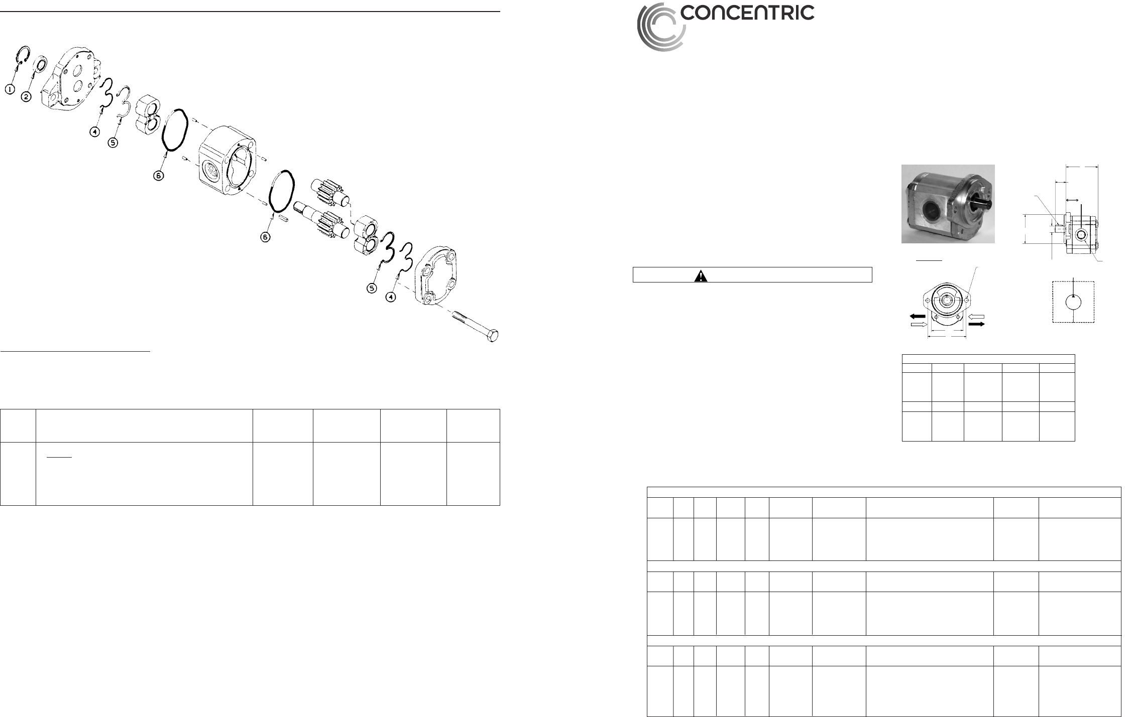
Figure 3 - Replacement Parts Illustration
Replacement Parts List
REF.
NO. DESCRIPTION W600 W900 W1500 QTY.
Seal Kit: 5400042 5000100 5200006 1
1 Snap Ring
2 Shaft Seal
4 Backup Ring
5 E-Seal
6 O-Ring
– 4 –
FORM 2690164 MODELS 10530-10535, 10597-10611
2690164 W600-900-1500 Series ENG_rev090111.indd 2-1 9/16/11 8:01 AM