
User Guide

Page 4 of 29
TM
dm10
In order to meet this challenge, the resulting circuits have particular
characteristics:
Ÿ First, all circuits in the preamp have distortion so low that it is
immeasurable, whether THD, IM etc.
Ÿ Second, all circuits in the preamp exhibit exceptionally low noise (see
specifications).
Ÿ Third, there is no compromise whatever with the choice of components
(Vishay resistors, FKP1 capacitors etc).
Ÿ Fourth, the circuits are highly immune to electromagnetic interference.
Some inputs and outputs include both first order filters and common
mode chokes.
Ÿ Fifth, the power supply and microprocessor circuits are designed for
minimal electromagnetic emissions (extensive 2
nd
to 6
th
order filters).
Ÿ Sixth, the power supply switching frequency was chosen to be much
higher than the audio band (>200kHz).
Ÿ Seventh, the power supply rails are exceptionally well regulated,
double regulation in fact (switch-mode and linear servo loops).
Ÿ Eighth, components and design are selected for high reliability.
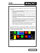
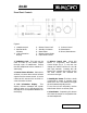
The figure below shows a functional block diagram of the preamplifier
(Diagram 1). As can be seen, the phono stage has 4 stages. Firstly, there is an
ultra low noise input stage with a gain of x 20 for moving coil cartridges. This
can be switched out of the circuit train.
Diagram 1