Indoor Unit Operation & Installation Manual MVAL009MV2AA MVAL012MV2AA MVAL018MV2AA MVAL024MV2AA MVAL030MV2AA MVAL036MV2AA MVAL042MV2AA MVAL048MV2AA No. 0150524546 • Please read this manual carefully before using. • Keep this operation manual for future reference.
User Manual Contents Parts and Functions ����������������������������������������������������������������������������������������������������������������������������������������������������������1 Safety ��������������������������������������������������������������������������������������������������������������������������������������������������������������������������������2 Maintenance ����������������������������������������������������������������������������������������������������������������������
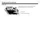
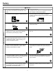
Parts and Functions Indoor unit Outlet guide plate (air direction can be adjusted by using direction adjustment key on the remote controller) Air-inlet grille Air filter (inside air-inlet grille) 1
Safety • This manual should be saved and stored close to this air conditioning equipment. • There are two types if indications. Both are related to safety and should be strictly followed. " Warning" highlights issues that pose a risk of major injury or death. " Caution" highlights issues that pose a risk of equipment or bodily injury. • After installation and start-up commissioning, please give the manual to the user. The manual should be kept in safe place and close to the unit.
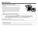
Safety Notices during Operation Attention • Do not put any heating apparatus under the indoor units. The heat may cause distortion of the units. • 3-minutes protection To protect the unit, there is a 3-minute time-out after the unit stops or after power is applied. • Pay attention to the ventilation to avoid anoxic injury. • Close the window to avoid outdoor air getting in. Curtains or window shutters can be put down to avoid the sunshine. • Do not place an open flame in the path of blowing air.
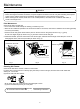
Maintenance Attention • Repair can only be performed by licensed service technicians. • Before touching the electrical connections, all power supplies should be turned off. Only after switching off the power supply can the operator clean the air conditioner otherwise there is a risk of electric shock or injury. • When cleaning the air cleaner, make sure to use a stable platform; don't flush the air conditioner with water, or electric shock might occur.
Maintenance Installing air cleaner and air inlet grid: 1. Mounting the filter: opposite of dismantling the filter (as shown in Fig. 3 above). 2.Mounting the air inlet grid: as shown in the right figure, clip the locks on the grid as directed by the arrows, put the side with the hinges into the lock port, and then put the side with locks into the panel frame. Release the locks to position the grid after determining that the grid is flush with the bottom of the panel frame.
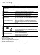
Fault Checkup Please make another check. All these are not problems Please check the following when consigning repair service: Symptoms Reasons Water flow sound Water flow sound can be heard during starting operation, during operation or immediately after stopping operation. When it starts for 2-3 minutes, the sound may become louder, which is the flowing sound of refrigerant or the draining sound of condensate water.
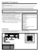
Installation Procedures Caution: Choose a suitable installation location. Avoid places with high salinity (salt water) and high sulfur gas. Unit will corrode and damage will not be covered by warranty. Avoid excess oil (including mechanical oil) and steam. This can reduce efficiencies and product performance. Avoid areas where machines generate high frequency electromagnetic waves. They can cause control issues. Warning: protect the machine from winds or earthquake, install according to regulations.
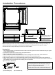
decorated board 38in (950mm) ceiling 36in (890mm) indoor unit 34in (850mm) gap between studs 31in (765mm) Installation Procedures gap between studs 31in (765mm) indoor unit 34in (850mm) Hanger bracket ceiling 36in (890mm) Model MVAL009~018MV2AA MVAL024MV2AA MVAL030~036MV2AA MVAL042~048MV2AA H 236 257 299 341 Ceiling Trim panel Distance between indoor unit and ceiling≤0.8in (20mm) Overlap between ceiling and trim panel≥1.
Installation Procedures Attention • For proper drainage, the drainpipes should be connected according to the installation manual. • Insulate the drainpipes to prevent exterior condensation. • Follow local plumbing codes when connecting drainpipes. Requirements: • The drainpipe of the indoor unit should be insulated. • Maintain a downward slope. Avoid waves or dips. • The horizon length of the drainpipe should be kept with 65.6ft(20m). Under the condition of long pipes, supports can be provided every 4.9-6.
lifting 14in (360mm) below Drain Test Test the drainpipe to confirm that there are no leaks or other issues with the drainpipe. • After system is fully installed and power is applied, turn on cooling operation and add water to check for drainage. • Confirm sound from the motor of the drainage pump and check for proper drainage. 3.9in(100 mm) below joint of drainpipe lifting 23.
Installation Procedures Installing the decorated panel on the body of indoor unit: receiving window for remote control the lamp will not flash when wired controller is used • Prior to attaching the panel to the unit locate the louver motor connector on the panel and the unit. Orientate the panel so they can connect. • First temporarily position it with screws. • Tighten each screw a little at a time to allow the panel to seat flush against the unit.
Electrical Wiring WARNING • Follow local codes when selecting wire gauge and connecting to house power. • Use the cable strain relief clips and locking conduit clamps to prevent wires from being pulled off terminal posts. • Unit must be properly grounded. Do not use water or gas piping, phone ground or lightning rod. Attention • Only copper wire can be used. A properly sized breaker should be provided, or electric shock may occur. • Unit requires 208/230VAC - 2 voltage wires and a ground. No neutral.
Electrical Wiring Signal Wiring Drawing Outdoor PQ Communication wire between indoor & outdoor without polarity Indoor 1 (950 CASSETTE) Indoor 3 Indoor 2 A BC PQ Control wire for wired controller with polarity PQA B C PQA B C A BC Indoor 5 Indoor 4 PQA B C A BC Indoor 7 Indoor 6 PQA B C A BC Wired controller PQA B C Wired controller A BC PQA B C Wired controller A BC Wired controller Indoor 9 Indoor 8 PQA B C Wired controller A BC PQA B C Wired controller A BC A BC Wired control
Electrical Wiring Wire gauge size and breaker size for total indoor amp draw. Current NEC guidelines and local codes will trump this chart. Items Total Current of Indoor Units(A) <7 ≥7 and <11 ≥11and <16 ≥16 and <22 ≥22 and <27 • • • • • Cross Section AWG (mm2) Length in.(m) Rated Current of Overflow Breaker(A) Rated current of residual Circuit Breaker(A) Ground Fault Interrupter(mA) Response time(S) Cross Sectional Area of Signal Line 14(2.5) 12(4) 10(6) 8(8) 6(10) 65.6(20) 65.6(20) 82(25) 98.
Electrical Wiring Dip Switch Setting • The dip switch is set to the "On" position if “1” is indicated in the table. The dip switch is set to the "Off" position if "0" is indicated in the table. • Dip switches set in the factory to on are marked with red. Definition principles of code switches: (A) Definition of SW01: SW01_1-4 is used to set indoor address when grouping multiple indoor units connected to single wired controller YRE16B or YR-E17. SW01_5-8 set capacity of the indoor unit (factory set).
Electrical Wiring Dip Switch Setting of YR-E17 Wired Controller Function switches DIP switch On/Off station On Sw1 Off On Sw2 Off On Sw3 Off On Sw4 Off On Sw5 Off On Sw6 Off On Sw7 Off On Sw8 Off Function Slave wired controller Master wired controller Ambient temp. display on Ambient temp. display off Collect ambient temp. from PCB of indoor Collect ambient Temp.
Test Run & Fault Code Before Test Run • Connect it to the power supply of the outdoor units to energize the heater of the compressor. To protect the compressor at startup, power it on 12 hours prior to the operation. Check if the connections of the drainpipe and wire connection lines are correct. The drainpipe shall be placed at the lower part while the connection line placed at the upper part.
Qingdao Haier Air Conditioner Electric Co.,Ltd. Haier Industrial Park,Qianwangang Road,Eco-Tech Development Zone,Qingdao 266555, Shandong,P.R.C.