
Service Guide
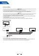
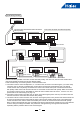
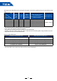
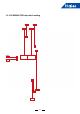
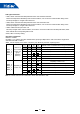
Table Of Contents

28
Dip switch introduction
Denition of SW01:
(A) SW01_1-4 is used to set indoor address when grouping multiple indoor units connected to single wired
controller YR-E16B or YR-E17.
SW01_5-8 set capacity of the indoor unit (factory set). Must only set when replacing board.
Note 1: A wired controller can control max. 16 DC slim duct indoor units.
SW01_1
SW01_2
SW01_3
SW01_4
Address of
wire controlled
indoor unit
(group
address)
(*Note 1)
[1] [2] [3] [4] Address of wire controlled indoor unit (group address)
OFF OFF OFF OFF 0# (wire controlled master unit) (default)
OFF OFF OFF
ON 1# (wire controlled slave unit)
OFF OFF
ON ON 2# (wire controlled slave unit)
OFF OFF
ON ON 3# (wire controlled slave unit)
… … … … ……
ON ON ON ON 15# (wire controlled slave unit)
SW01_5
SW01_6
SW01_7
SW01_8
Capability of
indoor unit
[5] [6] [7] [8] Capability of indoor unit
OFF OFF OFF
ON 7000BTU (MVAD007MV2AA)
OFF OFF
ON OFF 9000BTU (MVAD009MV2AA)
OFF OFF
ON ON 12000BTU (MVAD012MV2AA)
OFF
ON ON OFF 18000BTU (MVAD018MV2AA)
OFF
ON ON ON 24000BTU (MVAD024MV2AA)
LED light introduction:
• LED1, LED2: communication lamp between indoor unit and wired controller.
These two lamps icker alternately under normal condition; once occurs the communication faulty, these
two lamps will light or not light at the same time.
• LED3, LED4: communication lamp between indoor unit and outdoor unit.
These two lamps icker alternately under normal condition; once occurs the communication faulty, these
two lamps will light or not light at the same time.
• LED5: malfunction lamp of indoor unit.
This lamp not light under normal condition; once indoor unit occurs malfunction this lamp will icker, icker
times indicate the corresponding failure code.
•LED6, LED7: for factory testing