Slim Duct DC Service Manual SYJS-10-2018 REV.
CONTENTS 1. Features.................................................................................................................................................................1 2. Specification...........................................................................................................................................................2 3. Dimension................................................................................................................................................
1. Features MVAD007MV2AA MVAD009MV2AA MVAD012MV2AA MVAD018MV2AA MVAD024MV2AA 1.185mm height ultra thin design and 420mm depth 2. Built in drain pump 3. Ultra low noise: realize 21dB (A) operation noise 4. Rear air return 5. Static pressure 0-30Pa 6.
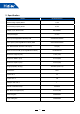
2. Specification MODEL MVAD007MV2AA Rated Cooling Capacity Btu/hr 7,500 Rated Heating Capacity Btu/hr 8,500 Voltage, Cycle, Phase V/Hz/- 208-230/60/1 Fan Speed Stages 5+Auto Airflow (Turbo/High/Med/Low/Quiet) CFM 540/480/420/360/300 Motor Speed (Turbo/High/Med/Low/Quiet) RPM 850/770/690/640/590 Max. External Static Pressure in.W.G (Pa) 0.
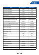
MODEL MVAD009MV2AA MVAD012MV2AA Rated Cooling Capacity Btu/hr 9,500 12,000 Rated Heating Capacity Btu/hr 10,500 13,500 208-230/60/1 208-230/60/1 5+Auto 5+Auto Airflow (Turbo/High/Med/Low/Quiet) CFM 540/480/420/360/300 640/550/430/370/330 Motor Speed (Turbo/High/Med/Low/Quiet) RPM 850/770/690/640/590 1100/1015/900/790/715 0.12(30) 0.
MODEL MVAD018MV2AA MVAD024MV2AA Rated Cooling Capacity Btu/hr 18,000 24,000 Rated Heating Capacity Btu/hr 20,000 27,000 208-230/60/1 208-230/60/1 5+Auto 5+Auto Airflow (Turbo/High/Med/Low/Quiet) CFM 950/800/690/580/440 1020/930/850/750/645 Motor Speed (Turbo/High/Med/Low/Quiet) RPM 1010/930/870/810/735 1180/1090/1010/920/825 0.12(30) 0.
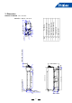
5 ④ 7 5/16(185) 3 1/2(90) 6 3/4(172) 6(152) 30 3/4(780) 33 7/16(850) 2 3/4(70) 25 1/4(640) 1 3/4(45) less than 7 7/8(200) 1 3/4(45) ⑥ ① ③⑤ drain hose with pump drain hose(accessory) checking hole drain outlet 4 5 6 gas pipe connection 2 1 1/2(40) 3 liquid pipe connection Part Name 7 1/4(184) 6 1/4(159) 1 5/8(42) 1 SN ② 1 1/4(30) 3 1/2 86 suspending bolt4-M10 3.
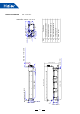
6 ④ 7 5/16(185) 3 1/2(90) 6 3/4(172) 6(152) 43 1/4(1100) 46 1/16(1170) 37 3/4(960) 1 3/4(45) 16 9/16(420) 2 3/4(70) less than 7 7/8(200) 1 3/4(45) ⑥ ① ③⑤ liquid pipe connection gas pipe connection drain hose with pump drain hose(accessory) checking hole drain outlet 2 3 4 5 6 Part Name 7 1/4(184) 6 1/4(159) 1 5/8(42) 1 SN ② 1 1/4(30) 3 1/2 86 suspending bolt4-M10 1 1/2(40) 6 1/4(160) MVAD018-024MV2AA unit:inch(mm) 0~23 1/2(0~600)adjustable
4.
5.
6. Electric characteristics Units Model MVAD007MV2AA MVAD009MV2AA MVAD012MV2AA MVAD018MV2AA MVAD024MV2AA Phase FQY 1 1 1 1 1 50/60 50/60 50/60 50/60 50/60 Power supply Indoor fan motor Voltage Volt range MCA MFA Output (W) FLA 220 220 220 220 220 198-242 198-242 198-242 198-242 198-242 0.24 0.24 0.38 0.38 0.59 0.76 0.76 1.2 1.2 2.12 50 50 50 45 45 0.19 0.19 0.3 0.47 0.53 Power input (w) Cooling Heating Symbols: MCA: Min. circuit amps (A) MFA: Max.
7. Air flow and static pressure curves MVAD007/009MV2AA air flow and static pressure curves 380 330 Air flow(CFM) Uhi 280 Hi Me 230 Lo 180 130 0.00 0.04 0.08 0.12 Static pressure(IWC) MVAD012MV2AA air flow and static pressure curves 380 330 Air flow(CFM) Uhi 280 Hi Me 230 Lo 180 130 0.00 0.04 0.08 Static pressure(IWC) 10 0.
MVAD018MV2AA air flow and static pressure curves 600 550 Air flow(CFM) 500 Uhi 450 Hi 400 Me 350 Lo 300 250 200 0.00 0.04 0.08 0.12 Static pressure(IWC) MVAD024MV2AA air flow and static pressure curves 700 650 Air flow(CFM) 600 550 Uhi 500 Hi Me 450 Lo 400 350 300 0.00 0.04 0.08 Static pressure(IWC) 11 0.
8. Sound pressure level Slim duct type running noise (1) Testing illustrate: The auxiliary air duct The auxiliary air duct Unit 1.4m Outlet side Air Sound level meter Testing position just below the central of the unit Note: The length of the auxiliary air duct is 2m (2) Testing condition: a. Unit running in the standard condition b. Test in the semi-anechoic chamber c. Noise level varies from the actual factors such as room structure, etc.
MVAD018MV2AA MVAD024MV2AA Octave band sound pressure level dB Octave band sound pressure level dB 70 60 50 40 30 20 10 Limit of audible continuous noise 63 70 60 50 40 30 20 Limit of audible continuous 10 noise 63 125 250 500 1000 2000 4000 8000 Octave band center frequency (HZ) 125 250 500 1000 2000 4000 8000 Octave band center frequency (HZ) 13
9. Installation 9.
9.2 Safety • This manual should be saved and stored close to this air conditioning equipment. • There are two types if indications. Both are related to safety and should be strictly followed. " highlights issues that pose a risk of major injury or death. " equipment or bodily injury. Warning" Caution" highlights issues that pose a risk of • After installation and start-up commissioning, please give the manual to the user. The manual should be kept in safe place and close to the unit.
Notices during Operation Attention • Do not put any heating apparatus under the indoor units. The heat may cause distortion of the units. • 3-minutes protection To protect the unit, there is a 3-minute time-out after the unit stops or after power is applied. • Pay attention to the ventilation to avoid anoxic injury. • Close the window to avoid outdoor air getting in. Curtains or window shutters can be put down to avoid the sunshine. • Do not place an open flame in the path of blowing air.
9.3 Maintenance Cleaning the air filter & air inlet grid. • Don't remove the air filter except for cleaning, or faults may occur. • When the air conditioner operates in the environment with too much dust, clean the air filter on a more regular basis (generally once every two weeks). Cleaning the Air Inlet/Outlet Grilles: Attention • Do not use gasoline, benzene, diluents, polishing powder or liquid insecticide to clean them.
9.4 Fault Checkup Please make another check. All these are not problems Please check the following when consigning repair service: Symptoms Reasons Water flow sound Water flow sound can be heard during starting operation, during operation or immediately after stopping operation. When it starts for 2-3 minutes, the sound may become louder, which is the flowing sound of refrigerant or the draining sound of condensate water.
9.5 Installation Procedures This manual cannot completely illustrate all the properties of the products you bought. Please contact the local Haier distribution center if you have any question or request. Caution: Choose a suitable installation location. Avoid places with high salinity (salt water) and high sulfur gas. Unit will corrode and damage will not be covered by warranty. Avoid excess oil (including mechanical oil) and steam. This can reduce efficiencies and product performance.
Dimension (unit: in.). Model MVAD007~12MV2AA MVAD018~24MV2AA a 16.5 16.5 b 35.1 47.7 c 14.6 14.6 d 33.5 46.1 e 7.3 7.3 f 25.2 37.8 b g 3.6 3.6 h 29.9 42.5 i 6.0 6.0 c a g e d f Dimensions of air outlet Hanger dimensions Dimensions of pump drainage hole, OD Ø1" h Air in Dimensions of natural drainage hole, OD Ø1" Dimensions of return air inlet Dimensions of drain hose Installation modes of Indoor unit This series of air conditioners can be arranged in two air return modes: 1.
˃40in (1000mm) Installation space ˃4in(100mm) Installation mode 4-Ø3/8"(M10)hanging bolt Electric control enclosure 8-Ø3/8"(M10) nut 8-Ø3/8"(Ø10) Washer Level the unit within 0.2in(5mm). If end A is to drain water, ensure end B is slightly higher than the end A to facilitate drainage. Otherwise, ensure end A is slightly higher than end B.
Installation of drain hose Connection of indoor drain hose 1. Please use the accessory drain hose to connect indoor unit's water outlet and PVC pipe. Use snap rings to tighten them as shown in the following figure: 2. Please use rigid PVC adhesive for connection of other pipes and ensure there is no leakage. 3. Drain hose must be wrapped with insulation sleeve and tightened with a strap to prevent air leakage from producing condensate. 4.
Pipe Length & Height Difference Please refer to the attached manual of outdoor units. Model Tubing Size in(mm) Tubing Material MVAD007~018MV2AA MVAD024MV2AA Gas pipe Ø1/2"(Ø12.7) Ø5/8"(Ø15.88) Liquid pipe Ø1/4"(Ø6.35) Ø3/8"(Ø9.52) Seamless copper pipe rated for R410A refrigerant Tubing Materials & Specifications Special tools for R410A should be used for cutting and enlarging pipes. Refrigerant Recharge Amount Add the refrigerant according to the installation instruction of outdoor unit.
9.6 Electrical Wiring WARNING • Follow local codes when selecting wire gauge and connecting to house power. • Use the cable strain relief clips and locking conduit clamps to prevent wires from being pulled off terminal posts. • Unit must be properly grounded. Do not use water or gas piping, phone ground or lightning rod. Attention • Only copper wire can be used. A properly sized breaker should be provided, or electric shock may occur. • Unit requires 208/230VAC - 2 voltage wires and a ground. No neutral.
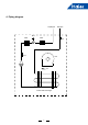
Signal Wiring Drawing Outdoor PQA B C Communication wire between indoor & outdoor without polarity Indoor 2 Indoor 1 P QA B C Control wire for wired controller with polarity Indoor 3 PQA B C PQA B C A BC Indoor 4 Indoor 5 PQA B C A BC Indoor 7 Indoor 6 PQA B C A BC Wired controller PQA B C Wired controller Indoor 8 PQA B C A BC A BC Wired controller Indoor 9 PQA B C Wired controller Wired controller A BC PQA B C Wired controller A BC A BC Wired controller Wired controller Outdoor
Wire gauge size and breaker size for total indoor amp draw. Current NEC guidelines and local codes will trump this chart. Items Total Current of Indoor Units(A) <7 ≥7 and <11 ≥11and <16 ≥16 and <22 ≥22 and <27 • • • • • Cross Section AWG (mm2) Length in.(m) Rated Current of Overflow Breaker(A) Rated current of residual Circuit Breaker(A) Ground Fault Interrupter(mA) Response time(S) Cross Sectional Area of Signal Line 14(2.5) 12(4) 10(6) 8(8) 6(10) 65.6(20) 65.6(20) 82(25) 98.
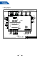
10.
LED light introduction: • LED1, LED2: communication lamp between indoor unit and wired controller. These two lamps flicker alternately under normal condition; once occurs the communication faulty, these two lamps will light or not light at the same time. • LED3, LED4: communication lamp between indoor unit and outdoor unit. These two lamps flicker alternately under normal condition; once occurs the communication faulty, these two lamps will light or not light at the same time.
(B) Definition and description of SW03 [1] [2] [3] [4] [5] [6] [7] [8] ON OFF OFF OFF OFF OFF OFF OFF SW03 Set the communication and central control address by dip switch (*Note 2) ON ON … ON ON ON ON … ON OFF OFF … OFF ON ON ON … ON OFF … OFF OFF … ON OFF OFF OFF … ON OFF OFF … ON OFF OFF OFF … ON OFF OFF … ON OFF OFF OFF … ON OFF OFF … ON OFF OFF OFF … ON OFF ON … ON OFF OFF ON … ON ON OFF … ON OFF ON OFF … ON … … … … … … Communication Central control address address 0 0 (default
11. Indoor unit control 11.1 Cooling operation Set temp. in cooling: Ts=set temp. wired controller; After startup, indoor unit will send the request to outdoor according to the temp. difference between the set temp. and the room temp. 11.2 Heating operation Set temp. in heating: Ts=set temp. wired controller+TA correcting value. After startup, indoor unit will send the request to outdoor according to the temp. difference between the set temp. and the room temp. 11.3 Dry operation Room temp. - set temp.
11.8 Anti-freezed protection In cooling mode, execute the anti-freezed protection due to the measured indoor coil temp. to avoid the indoor heat exchanger causing frost or ice. 11.9 Swing motor control Indoor will control swing motor ON/OFF due to the swing signal from wired controller. 11.10 Auxiliary electric heater control In heating mode, if the below conditions can be met, the electric heater will work: (1) Indoor fan motor and compressor are running; (2) Air inlet temp.
12. Failure code Failure code at wired controller (hex) PCB LED5(Indoor Units)/ Receiver Timer Lamp(Remote Controller) 01 1 Indoor ambient temp. sensor TA failure 02 2 Indoor coil pipe temp. sensor TC1 failure 03 3 Indoor coil pipe temp.
13.
[05] EEPROM failure No If the chip is fixed well Reconnect Yes Yes If the chip is damaged Replace it No Check if PCB is faulty, if yes, replace it [09] Indoor address repeated No If wiring between P and Q is normal Modify the wiring Yes Yes If communication wire is connected with multi outdoors No If indoor QTY connected with outdoor is normal No Yes Check outdoor connecting board, if faulty, replace it 34 Modify the communication wire
[06] Communication circuit between indoor and outdoor If wiring between P and Q is wrong or broken down Yes Modify the communication wire No If the port of CN15 on indoor PCB is normal No Modify the port Yes If the port of CN19 on outdoor connecting board is normal No Yes Yes If outdoor power source is normal Electrify the outdoor No Yes If power supply is failure Clear the failure code No Yes If there is noise No Check outdoor PCB, if faulty, replace it 35 Check and eliminate noise
[07] Communication abnormal between indoor and wired controller If wiring of terminal A, B, C of wired controller is proper No Modify the wiring Yes If the broken wire or port is fixed improperly Yes Modify the connection No If in group operation No If there is indoor unit set as No. 0 If there are multi indoors set as No. 0 If there is indoor unit set as No. 0 No No No Yes Set one indoor unit as No. 0 Set only one indoor unit as No. 0 Set one indoor unit as No.
[12] No 50Hz zero passage signal No Check if the transformer is well Replace transformer Yes Check if the wiring of the wired controller connect well Yes Replace PCB 37 No Reconnect
[14] DC motor failure Check if the wiring of motor is fixed well No Reconnect Yes Yes If the motor is fault No Replace the PCB 38 Replace motor
[18] The 4-way valve of 3-pipe valve box reversing failure If the 4-way valve of 3-pipe Yes valve box is internal leakage Adjust it correctly by after-sales personnel on site. No Check if the TC1 and TC2 of indoor unit are normal, if the resistance is right? If the connect well? No Adjust it correctly by after-sales personnel on site. Yes If the 4-way valve of outdoor unit is internal leakage No Adjust it correctly by after-sales personnel on site.
14. Capacity (CA: total capacity; SHC: sensible heat capacity) Cooling Model Outdoor temp. °F DB MVAD007 MV2AA MVAD009 MV2AA MVAD012 MV2AA MVAD018 MV2AA MVAD024 MV2AA 68 72.5 77 81.5 86 90.5 95 99.5 104 109.4 68 72.5 77 81.5 86 90.5 95 99.5 104 109.4 68 72.5 77 81.5 86 90.5 95 99.5 104 109.4 68 72.5 77 81.5 86 90.5 95 99.5 104 109.4 68 72.5 77 81.5 86 90.5 95 99.5 104 109.4 70.
Heating Model MVAD007MV2AA MVAD009MV2AA MVAD012MV2AA MVAD018MV2AA MVAD024MV2AA Outdoor temp. °FDB 5 14 23 32 36.5 42.8 43.7 50 54.5 59.9 5 14 23 32 36.5 42.8 43.7 50 54.5 59.9 5 14 23 32 36.5 42.8 43.7 50 54.5 59.9 5 14 23 32 36.5 42.8 43.7 50 54.5 59.9 5 14 23 32 36.5 42.8 43.7 50 54.5 59.9 Indoor temp.(°FDB) 68.0 77.
Haier Commercial Air Condition Web: Http://www.haier.com Haier reserves the right to make change without any notice.